
Key switch for electronic piano

Active Publication Date: 2013-03-28
KAWAI MUSICAL INSTR MFG CO
View PDF23 Cites 7 Cited by
  • Summary
  • Abstract
  • Description
  • Claims
  • Application Information

AI Technical Summary

Benefits of technology

The present invention provides a key switch for an electronic piano that allows for a larger range of contact shifting without increasing the size of the key switch. This prevents errors and provides precise detection of key depression. Additionally, the key switch ensures reliable contact between each contact during the pivotal motion of a pivotal member, resulting in a stable switching operation and further accurate detection of key depression information.

Problems solved by technology

For this reason, when the contact position of the movable contact shifts in the front-rear direction and the movable contact deviates even slightly from the stationary contact, the movable contact can be erroneously brought into contact with an adjacent stationary contact, causing erroneous detection.
However, when the movable contact of the conventional key switch has an increased diameter, it is more likely that the movable contact is brought into contact with an adjacent stationary contact due to shift of its contact position, and therefore the magnitude of the diameter of the movable contact has to be limited.
However, since the entire length of the key switch of the three-contact type is originally larger than that of a key switch of the two-contact type, the above-mentioned method further increases the entire length of the key switch, which causes an increase in the size of the key switch.
There is another problem.
However, when the conventional technique is applied to the key switch of the three-contact type, there is a fear that stable switching operation cannot be ensured for reasons mentioned below, and therefore there remains room to be improved in this point.
This sometimes makes it impossible to bring the third movable contact into secure contact with the third stationary contact, which can cause a faulty operation.
With this arrangement, however, the first movable contact having already been in contact with the first stationary contact is apt to move up from the first stationary contact during halfway through a pivotal motion of the hammer, which makes it difficult to maintain the contact state.
Therefore, also in this case, there is a fear that a faulty operation can be caused.
In this case, however, difference in output timing between the ON signals is reduced, which causes degradation of accuracy in detecting the hammer motion.

Method used


Image

  • Key switch for electronic piano
  • Key switch for electronic piano
  • Key switch for electronic piano

Examples


Embodiment Construction

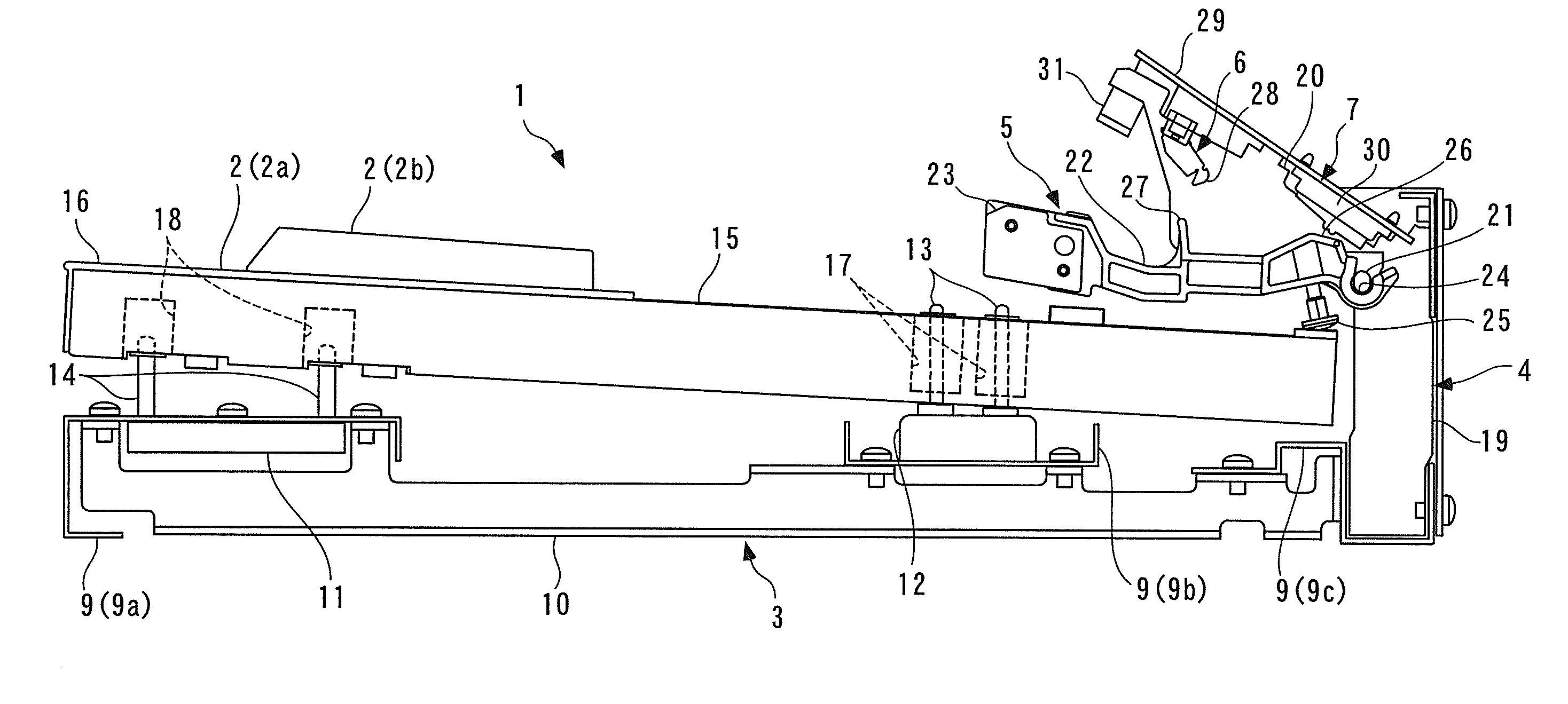
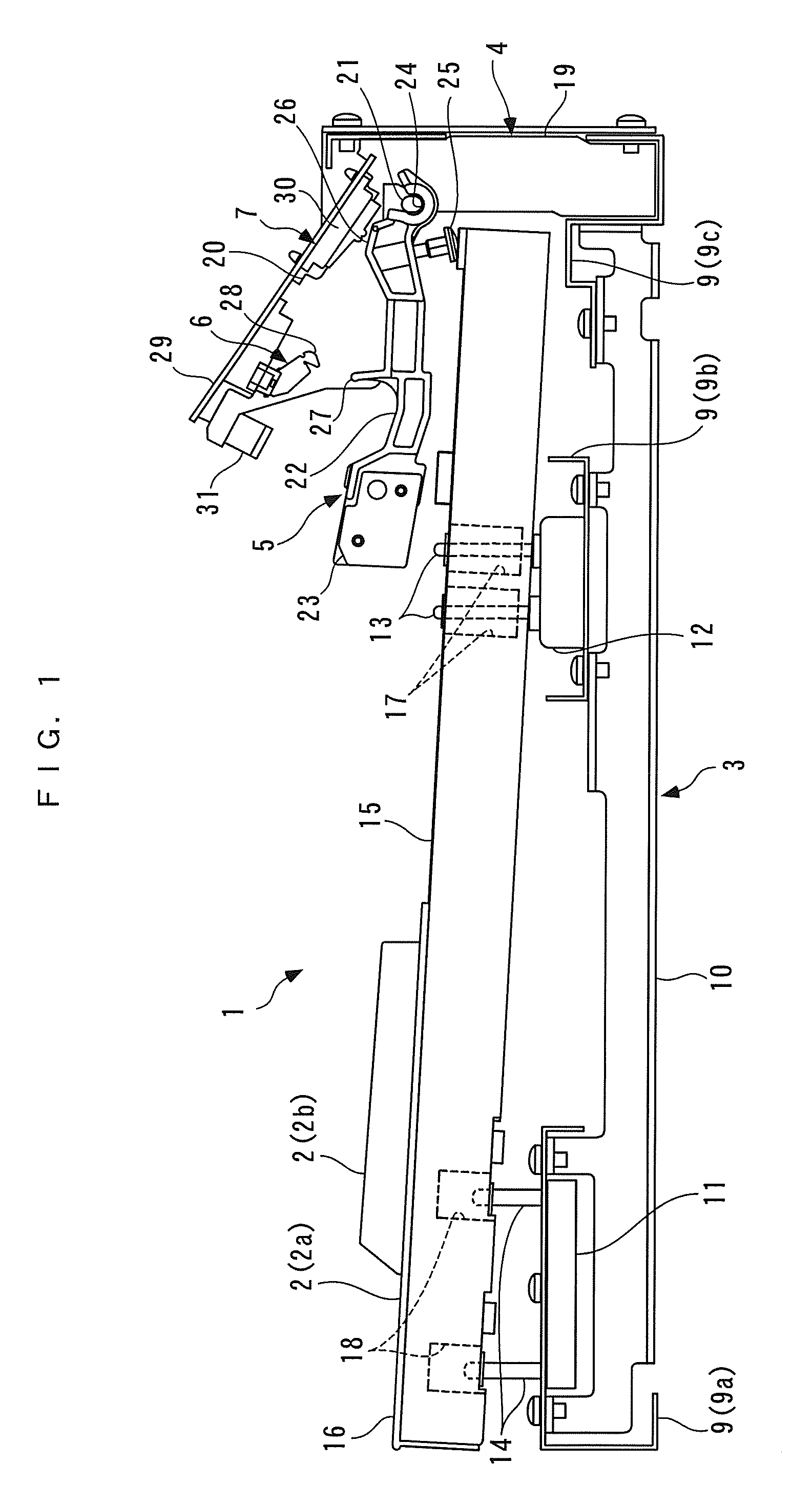
[0048]The present invention will now be described in detail with reference to the drawings showing a preferred embodiment thereof. FIG. 1 shows a keyboard device for an electronic piano, according to the embodiment of the present invention, in a key-released state.

[0049]As shown in FIG. 1, the keyboard device 1 includes a plurality of keys 2 (only one of white keys 2a and one of black keys 2b are shown) arranged side by side in a left-right direction (depth direction as viewed in FIG. 1) of the electronic piano, a keyboard chassis 3 for supporting the keys 2, a hammer support 4 connected to the rear end (right end as viewed in FIG. 1) of the keyboard chassis 3, a plurality of hammers 5 (only one of which is shown) each provided for an associated one of the keys 2, for being pivotally moved in accordance with depression of the key 2, a plurality of let-off members 6 (only one of which is shown) each provided for an associated one of the hammers 5, for adding a let-off feeling to the ...


PUM


Abstract

A key switch for an electronic piano, which makes it possible to increase an allowable range for shift of a movable contact without increasing the size of the key switch of the three-contact type. The key switch includes a substrate having first to third stationary contacts arranged thereon side by side in the lengthwise direction of a pivotal member as one of a key and a hammer. Each stationary contact has a common contact and a non-common contact. The common contact has an extended portion extending between two non-common contacts. The key switch has first to third movable contacts arranged side by side on an elastic switch body, for being sequentially brought into contact with the common contacts and non-common contacts of the stationary contacts as the switch body is pressed by the pivotal member, to thereby output signals indicative of key depression information.

Description

BACKGROUND OF THE INVENTION[0001]1. Field of the Invention[0002]This invention relates to a key switch for an electronic piano, which is configured to detect a motion of a key or a hammer that pivotally moves in accordance with depression of the key, as key depression information.[0003]2. Description of the Related Art[0004]Conventionally, the above-mentioned type of key switch for an electronic piano has been disclosed e.g. in Japanese Laid-Open Patent Publication (Kokai) No. 2007-52357. The key switch is of a three-contact type that detects a motion of a key in three stages. The key switch is comprised of a dome-shaped rubber switch fixedly secured to the lower surface of the key and a switch board disposed below the rubber switch. The rubber switch has cylindrical first to third switch elements extending vertically downward from the top wall and arranged in a front-rear direction (lengthwise direction) of the key. The first switch element is the longest of all the first to third ...

Claims


Application Information

Patent Timeline
IPC IPC(8): G10H1/34
CPCG10H2220/285G10H1/346
Inventor IWASE, MASAHIKOISHIDA, HIDEYUKI
Owner KAWAI MUSICAL INSTR MFG CO
Learn More