
Structure of self-opening/closing umbrella

Inactive Publication Date: 2013-03-28
LIU YUNG HSIANG
View PDF8 Cites 6 Cited by
  • Summary
  • Abstract
  • Description
  • Claims
  • Application Information

AI Technical Summary

Benefits of technology

The present invention provides a self-opening / closing umbrella that allows for easier operation and reduces potential risk. The invention achieves this by simultaneously moving downward the runner and third shaft segment to shorten the central shaft unit when closing the umbrella. The operation of compressing and closing the umbrella is made easy, and potential risk is significantly reduced. Additionally, the invention shortens the overall length of the umbrella opening spring to avoid hurting during compressing and closing, while also preventing the spring from interfering with the movement of the inner tube. The invention design allows for convenient and easy operation of the umbrella with a pushbutton and pull ropes.

Problems solved by technology

(1) Pressing down the pushbutton to close the umbrella only collapse the ribs and a canopy of the umbrella, and the central shaft unit is still kept in a condition where the three segments are fully extended to set the umbrella in the greatest length thereof. It is difficult for a woman or a child whose hands are relatively short to hand grip and compress the central shaft unit toward the handle for completely closing the umbrella.
(2) The umbrella opening spring that normally shows a length spanning from the first shaft segment to the top end of the third shaft segment is of quite a strength and spring force, so that a user must apply a great force with his or her hands to compress and close the umbrella. This makes it difficult for a woman or a child whose hands are of relatively weak physical strength to compress and close the umbrella.
(3) Since the strength and spring force of the umbrella opening spring are great, if, in an attempt to close the umbrella, the application of force or the operation of closing the umbrella is in error, the compressed umbrella opening spring will spring the central shaft unit back with a great force. This often hurts the hands or other portions of the body of the user.
Thus, the known self-opening / closing umbrella is of a design that is imperfect and may cause inconvenience and danger in the use thereof.

Method used


Image

  • Structure of self-opening/closing umbrella
  • Structure of self-opening/closing umbrella
  • Structure of self-opening/closing umbrella

Examples


Embodiment Construction

[0022]The following descriptions are exemplary embodiments only, and are not intended to limit the scope, applicability or configuration of the invention in any way. Rather, the following description provides a convenient illustration for implementing exemplary embodiments of the invention. Various changes to the described embodiments may be made in the function and arrangement of the elements described without departing from the scope of the invention as set forth in the appended claims.

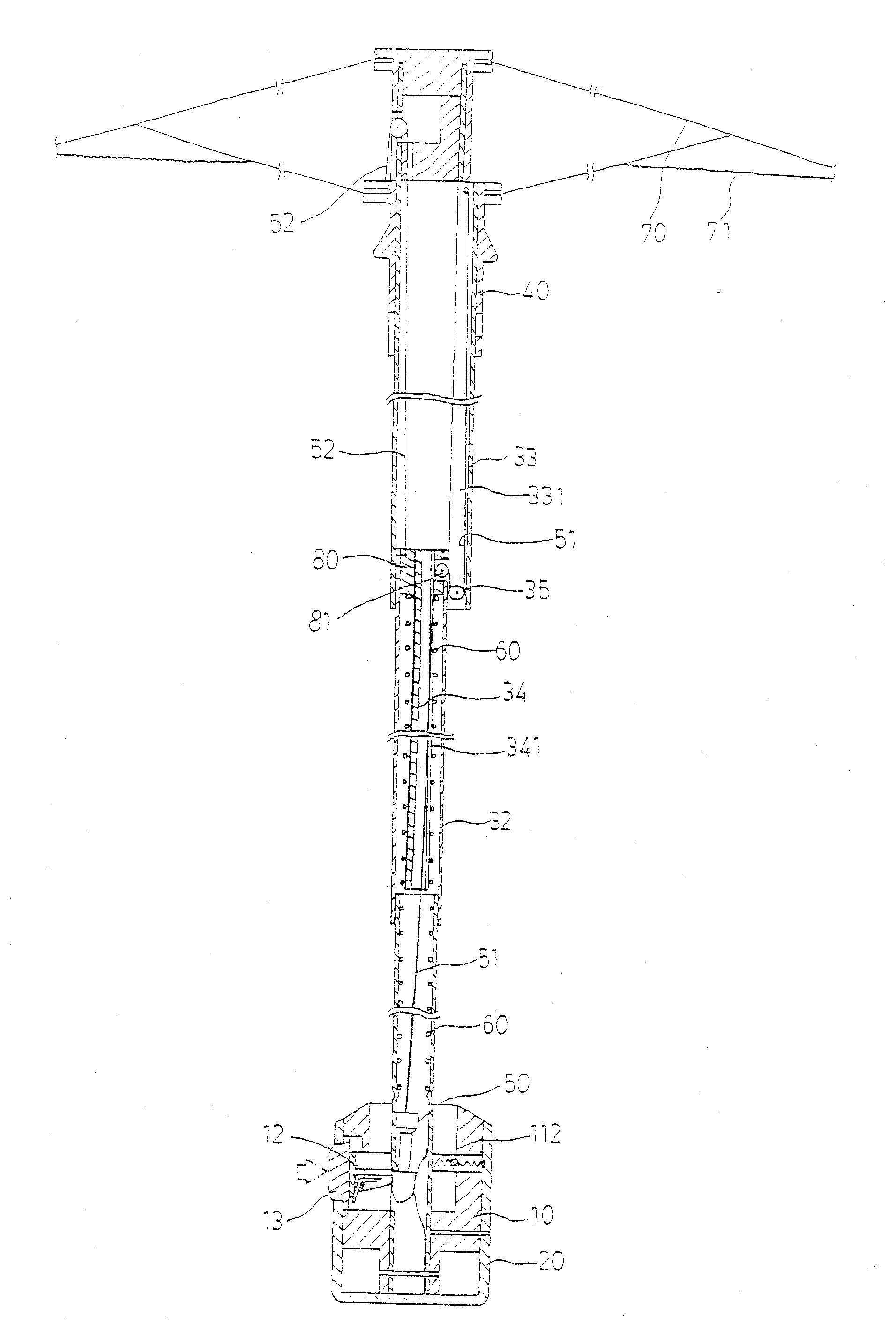
[0023]Referring to FIG. 4, the present invention provides a self-opening / closing umbrella that will be explained by taking a three-folded umbrella as an example. The umbrella generally comprises an operation unit (10), a handle (20), a central shaft unit (30), a runner (40), a top cap (41), a bullet-head member (50), an umbrella opening spring (60), and a plurality of ribs (70) and umbrella closing springs (71). The operation unit (10) is arranged inside the handle (20) and comprises a body having a...


PUM


Abstract

A self-opening / closing umbrella includes a central shaft unit having an improved structure. The central shaft unit forms a raised channel on one side of a third shaft segment and a pulley is pivotally mounted to a lower portion of the raised channel. A second shaft segment has a top to which an internal plug including a pulley is fixed and includes a first pull rope having an end fixed to a bullet-head member and an opposite end extending upward to warp around the pulley of the internal plug, projecting through a sideway slot, extending downward to wrap around the pulley inside the third shaft segment for upward extension to fix to a top end of the third shaft segment. A second pull rope has an end fixed to the internal plug and an opposite end extending across a top cap to project outward to fix to the runner.

Description

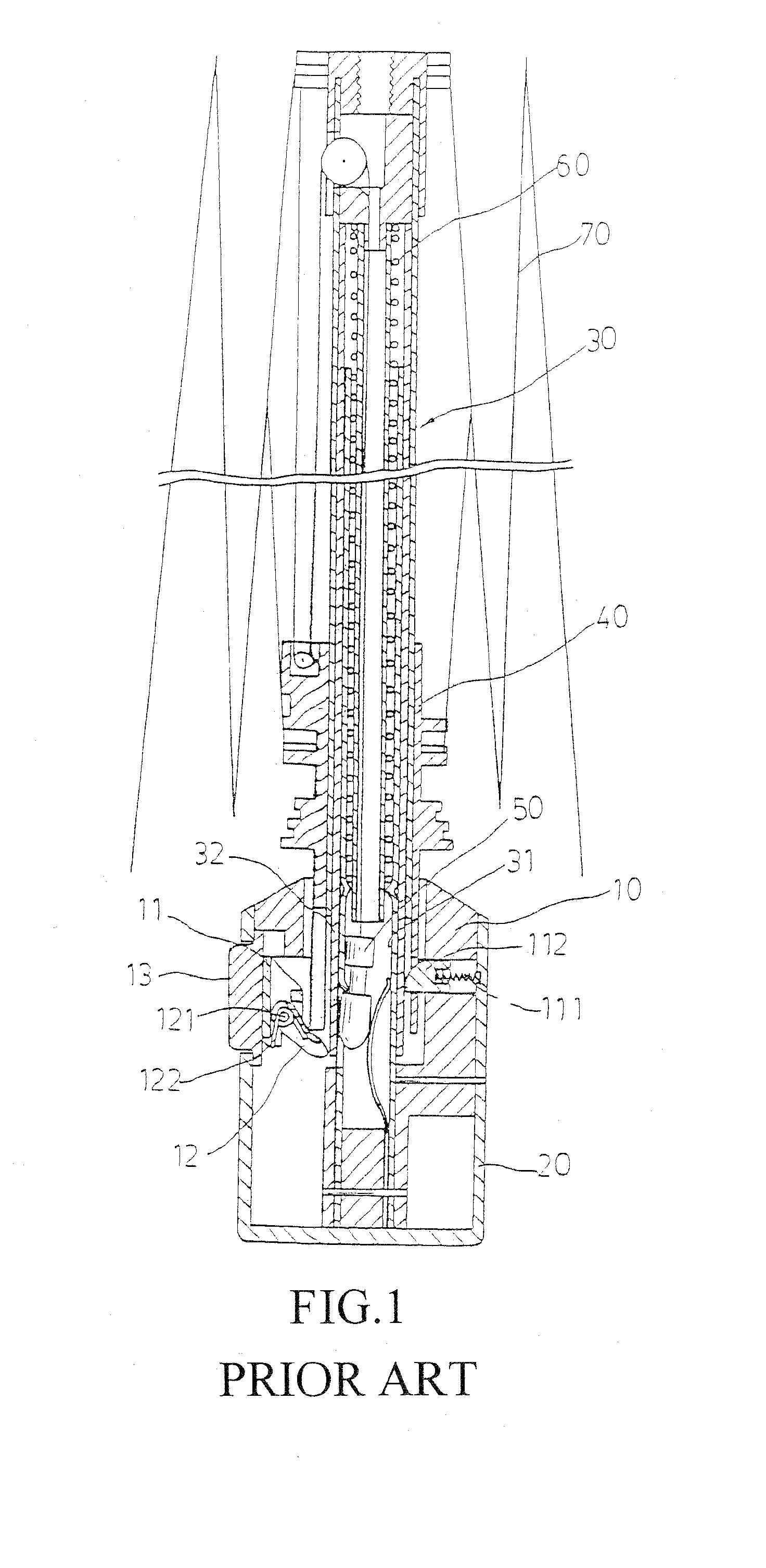
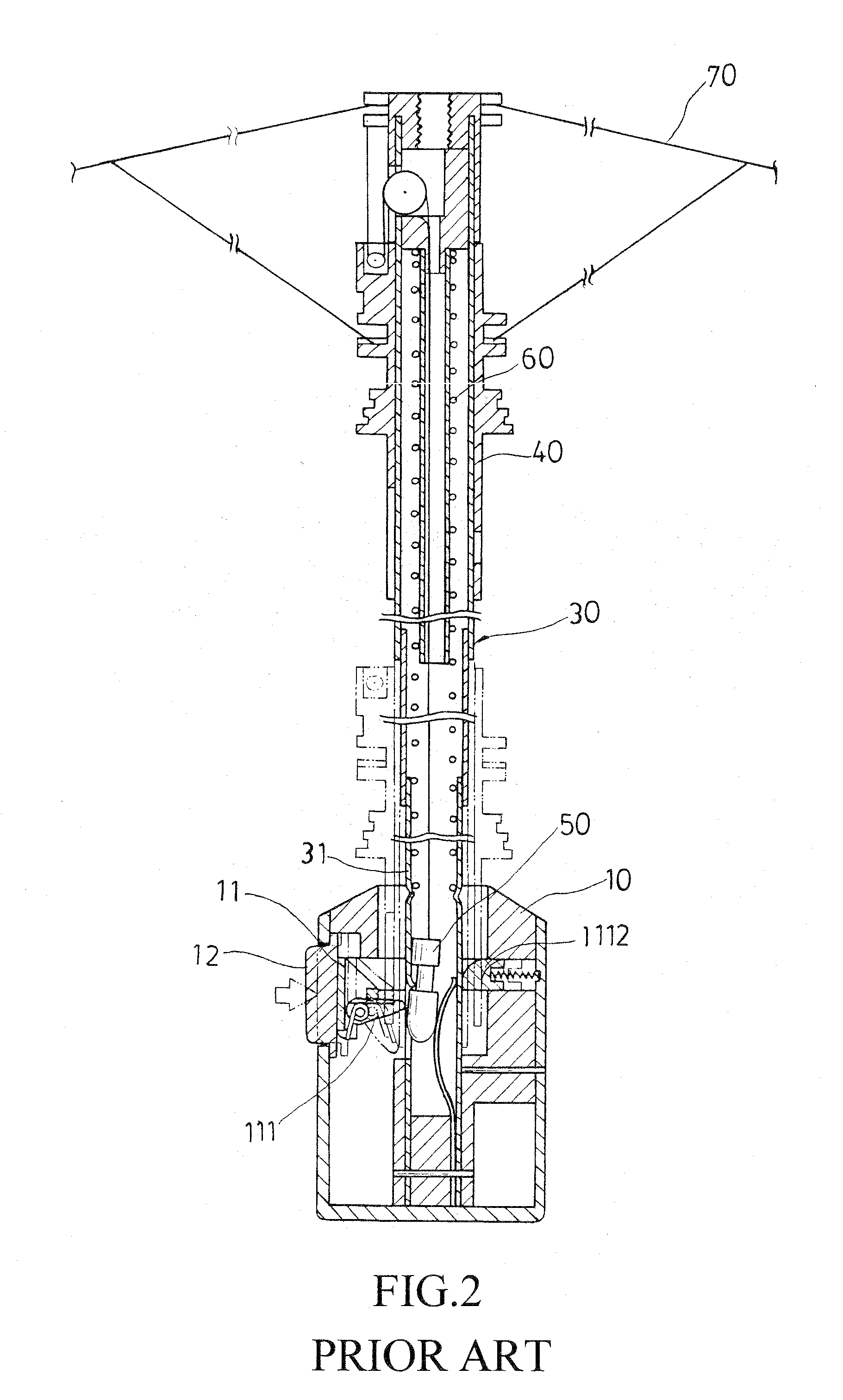
TECHNICAL FIELD OF THE INVENTION[0001]The present invention generally relates to a structural improvement of self-opening / closing umbrella, which comprises an improvement of the configuration of a central shaft unit of a self-opening / closing umbrella so that the improved self-opening / closing umbrella allows easy accomplishment of the final compression for closing the umbrella thereby significantly reducing the risk caused by the compression and closing operation of umbrella.DESCRIPTION OF THE PRIOR ART[0002]The structure and operation of a commonly seen self-opening / closing umbrella are generally illustrated in FIGS. 1-3, wherein a three-folded umbrella is taken as an example for explanation, which generally comprises a handle (20) inside which an operation unit (10) is provided, a central shaft unit (30) inside which an umbrella opening spring (60) is received, and a runner (40) coupled to ribs (70) and comprising a pulley around which a pull rope (51) having an end fixed to a top ...

Claims


Application Information

Patent Timeline
IPC IPC(8): A45B25/16
CPCA45B25/143A45B25/16
Inventor TAN, HONG-WEI
Owner LIU YUNG HSIANG
Learn More