Electric rotating machine

a technology of rotating machines and rotating coils, which is applied in the direction of dynamo-electric components, ac commutators, dynamo-electric machines, etc., can solve the problem of no bridging wires, and achieve the effect of minimizing the negative mutual inductance therebetween, reducing the total inductance of the stator coil, and weakening the magnetic coupling

Active Publication Date: 2013-03-28
DENSO CORP +1
View PDF3 Cites 17 Cited by
  • Summary
  • Abstract
  • Description
  • Claims
  • Application Information

AI Technical Summary

Benefits of technology

[0034]With the above configuration, for each of the sub-windings of the phase windings of the stator coil, the first and second halves of the sub-winding are respectively received in two different single-phase slots for the phase winding. Consequently, it is possible to weaken the magnetic coupling between the first and second halves of the sub-winding, thereby minimizing the negative mutual inductance therebetween. Thus, it is possible to

Problems solved by technology

However, there is no bridging wire that radiall

Method used


Image

  • Electric rotating machine
  • Electric rotating machine
  • Electric rotating machine

Examples


first embodiment

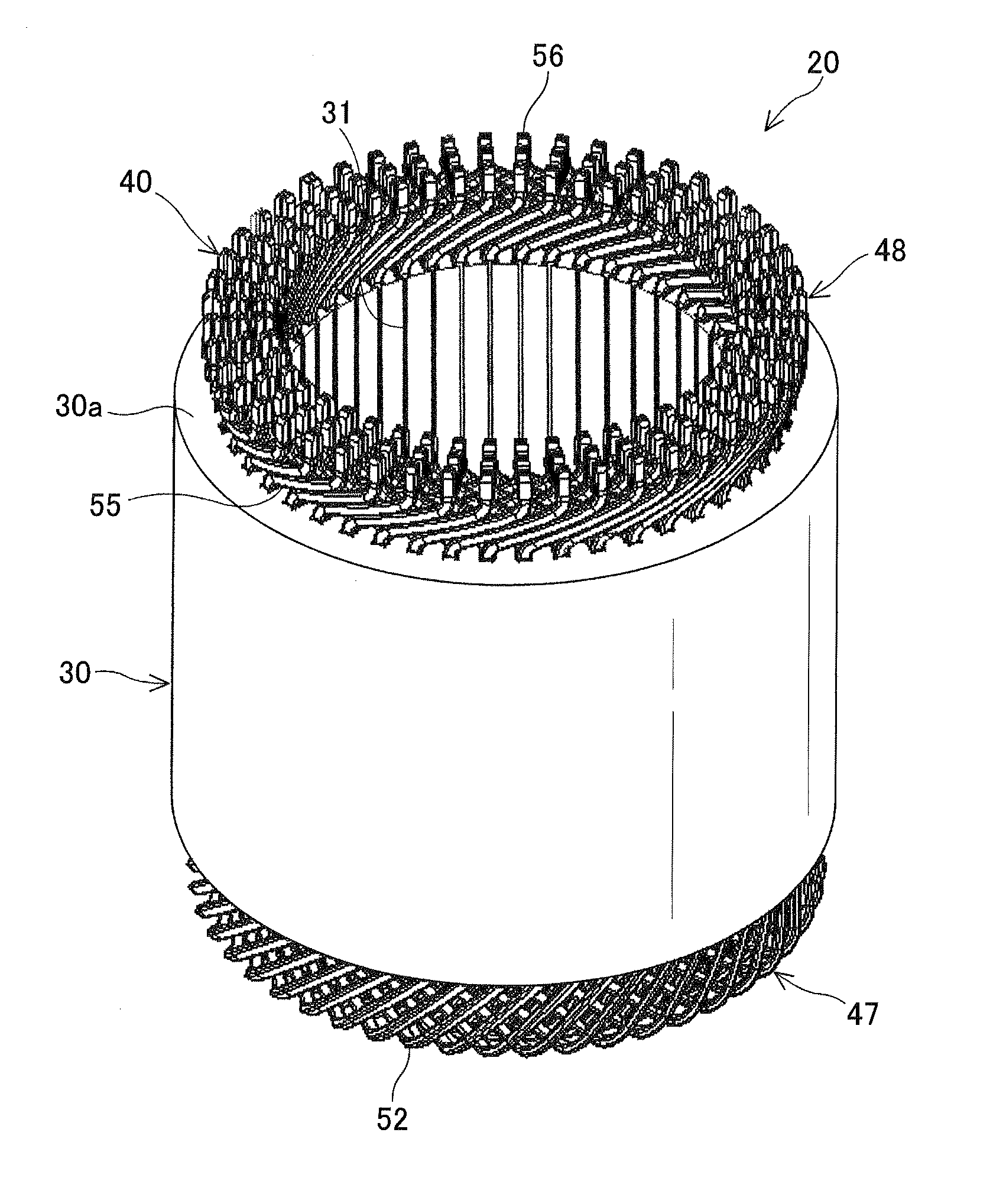
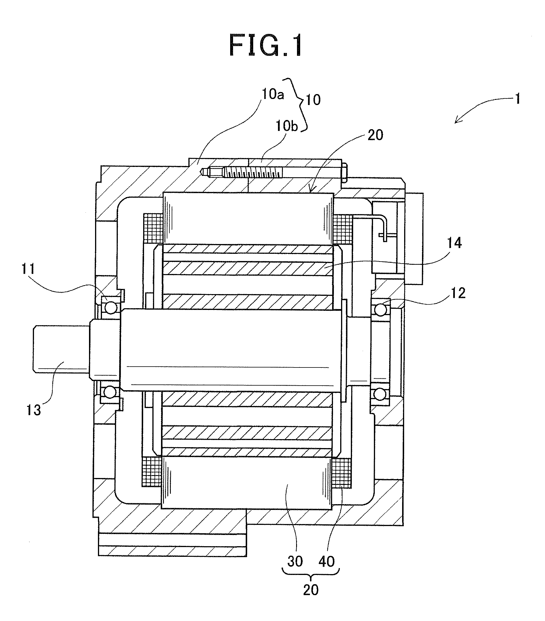
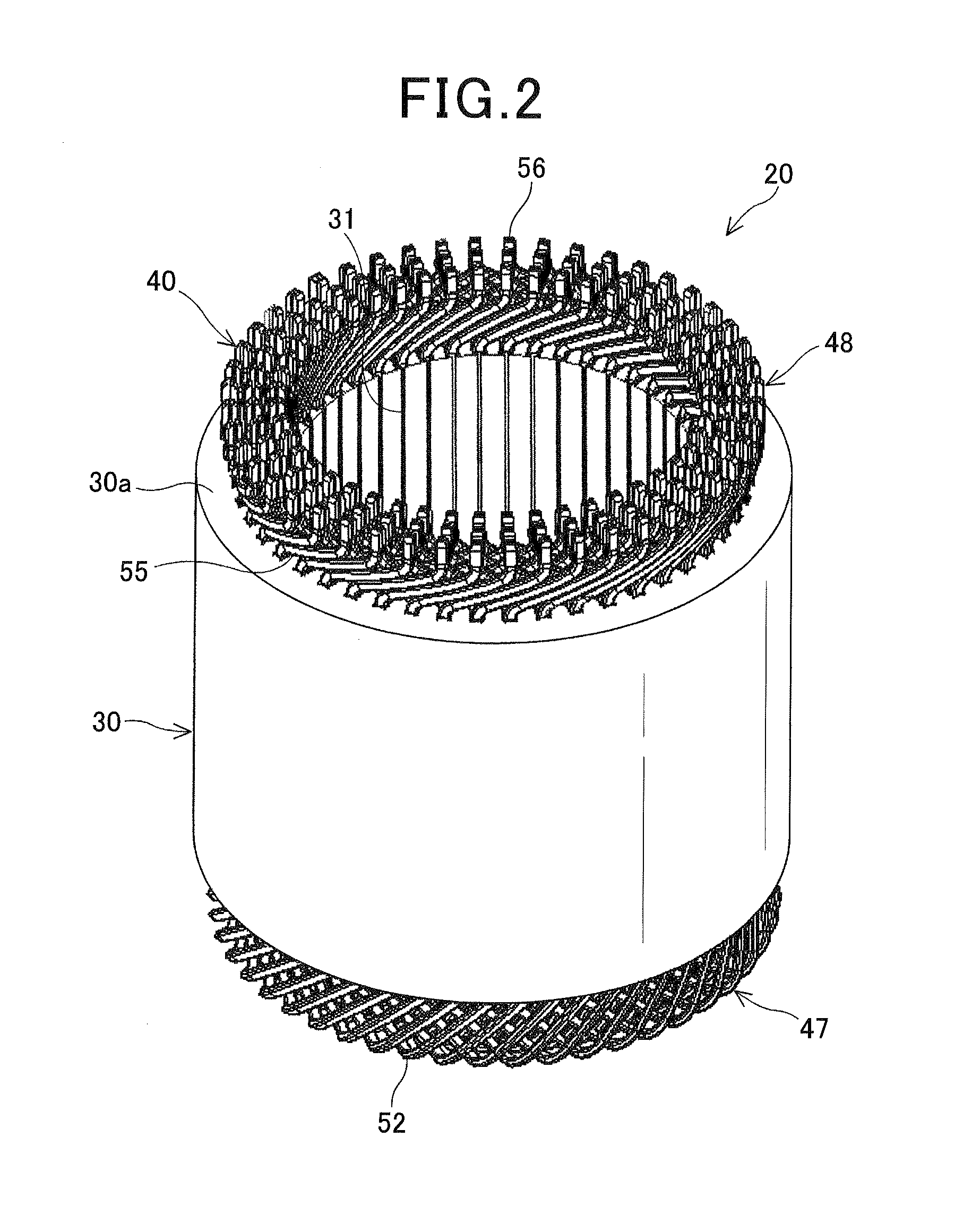
[0071]FIG. 1 shows the overall configuration of an electric rotating machine 1 according to a first embodiment. The electric rotating machine 1 is designed to be used in a motor vehicle to function as an electric motor.

[0072]As shown in FIG. 1, the electric rotating machine 1 includes a housing 10, a rotor 14 and a stator 20. The housing 10 is comprised of a pair of substantially cup-shaped housing pieces 10a and 10b which are jointed together at the open ends thereof. The housing 10 has a pair of bearings 11 and 12 mounted therein, via which a rotating shaft 13 is rotatably supported by the housing 10. The rotor 14 is received in the housing 10 and fixed on the rotating shaft 13. The stator 20 is fixed in the housing 10 so as to surround the radially outer periphery of the rotor 14.

[0073]The rotor 14 includes a plurality of permanent magnets that are embedded at predetermined positions in the rotor 14. The permanent magnets form a plurality of pairs of N and S magnetic poles on the...

experiment 1

[Experiment 1]

[0105]This experiment has been conducted to verify the effect of lowering the maximum phase-to-phase voltage of the stator coil 40 according to the first embodiment.

[0106]Specifically, in the experiment, an electric rotating machine was used in which: the stator core had two single-phase slots per phase winding of the stator coil and per magnetic pole of the rotor; and the phase windings of the stator coil were wave-wound on the stator core so as to be radially stacked in six layers in each slot of the stator core. Moreover, with the electric rotating machine, three different stator configurations were realized by changing the sequence of electrically connecting different sections of the phase windings of the stator coil.

[0107]The first configuration was the conventional one as shown in FIG. 27A. The second configuration was the conventional one as shown in FIG. 28A. In both the first and second conventional configurations, for each phase winding of the stator coil, th...

first modification

[First Modification]

[0111]In this modification, as shown in FIGS. 10A and 10B, each of the phase windings 41 of the stator coil 40 is formed by joining eight continuous electric wires 60, not by joining the electric conductor segments 50 as in the first embodiment.

[0112]Specifically, each of the electric wires 60 includes twelve in-slot portions (not shown), each of which is received in a corresponding one of the slots 31 of the stator core 30, and eleven turn portions 62 that each connect a corresponding adjacent pair of the in-slot portions and are alternately located on opposite axial sides of the stator core 30. Further, among the twelve in-slot portions, the first in-slot portion which is formed at one end of the electric wire 60 is received in the first layer (i.e., the radially innermost layer) of one slot 31 of the stator core 30, while the twelfth in-slot portion which is formed at the other end of the electric wire 60 is received in the sixth layer (i.e., the radially oute...


PUM


Abstract

An electric rotating machine includes a rotor and a stator. The rotor has a plurality of pairs of magnetic poles. The stator includes a stator core and a stator coil that is comprised of a plurality of phase windings wound on the stator core. The stator core has, for each of the phase windings of the stator coil, n circumferentially-consecutive single-phase slots, in which only the phase winding is received, per magnetic pole of the rotor, where n is a natural number not less than 2. Each of the phase windings of the stator coil has first to kth sections that are sequentially arranged from one end to the other end of the phase winding, where k is a natural number not less than 2. The first section is received in different ones of the single-phase slots for the phase winding from the kth section.

Description

CROSS-REFERENCE TO RELATED APPLICATIONS[0001]This application is based on and claims priority from Japanese Patent Applications No. 2011-208278 filed on Sep. 24, 2011, No. 2012-15596 filed on Jan. 27, 2012, and No. 2012-148570 filed on Jul. 2, 2012, the contents of which are hereby incorporated by reference in their entireties into this application.BACKGROUND[0002]1. Technical Field[0003]The present invention relates to electric rotating machines that are used in, for example, motor vehicles as electric motors and electric generators.[0004]2. Description of the Related Art[0005]There are known electric rotating machines which include a rotor and a stator. The rotor has a plurality of pairs of magnetic poles that are arranged in a circumferential direction of the rotor. The stator includes a stator core and a stator coil. The stator core has a plurality of slots, which are arranged in a circumferential direction of the stator core, and is radially opposed to the rotor. The stator coi...

Claims


Application Information

Patent Timeline
IPC IPC(8): H02K3/28
CPCH02K3/28
Inventor IKEDA, KAZUMASAWAKIMOTO, TORUTAKAHASHI, YOSHIMITSU
Owner DENSO CORP
Why Eureka
Try Eureka