
2-d straight-scan on imaging surface with a raster polygon

a raster polygon and imaging surface technology, applied in the field of laser-based image generation systems, can solve the problems of degrading viewing experience, affecting image processing and timing, and directing lasers not following straight lines

Active Publication Date: 2013-03-28
PRYSM SYST INC
View PDF5 Cites 30 Cited by
  • Summary
  • Abstract
  • Description
  • Claims
  • Application Information

AI Technical Summary

Benefits of technology

The present invention allows for the use of a single high-speed rotational element to quickly scan light onto an imaging surface with straight and parallel scan lines. This results in ultrafast and efficient imaging.

Problems solved by technology

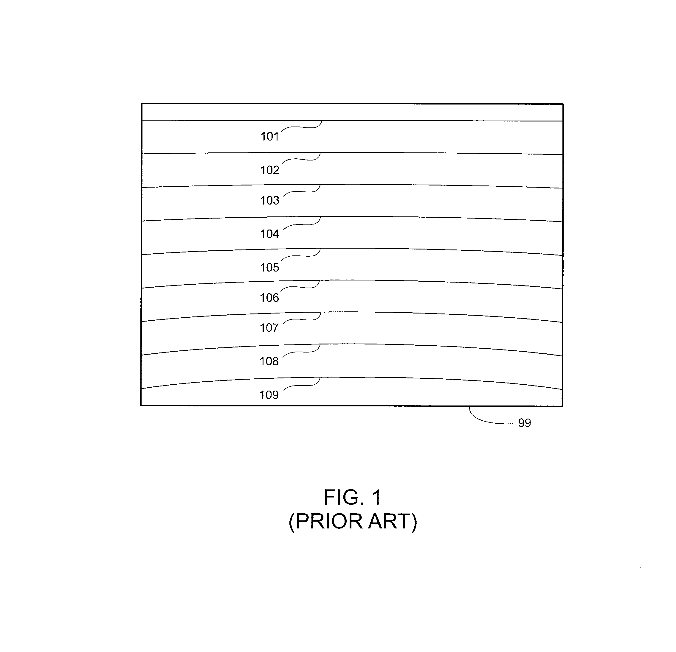
A drawback to using a raster polygon mirror for scanning lasers across an image-generating surface is that the lasers so directed do not follow straight lines across the image generating surface.
Instead, the scan lines of the lasers have significant curvature, which greatly complicates image processing and timing.
Such distortion is primarily caused by asymmetrical rotation properties of the different reflective facets and by distortion of the scan-imaging optics that focus the laser on the imaging surface.
Such distortion of laser scan lines 101-109 is generally visible to a viewer and can result in a degraded viewing experience.

Method used


Image

  • 2-d straight-scan on imaging surface with a raster polygon
  • 2-d straight-scan on imaging surface with a raster polygon
  • 2-d straight-scan on imaging surface with a raster polygon

Examples


Embodiment Construction

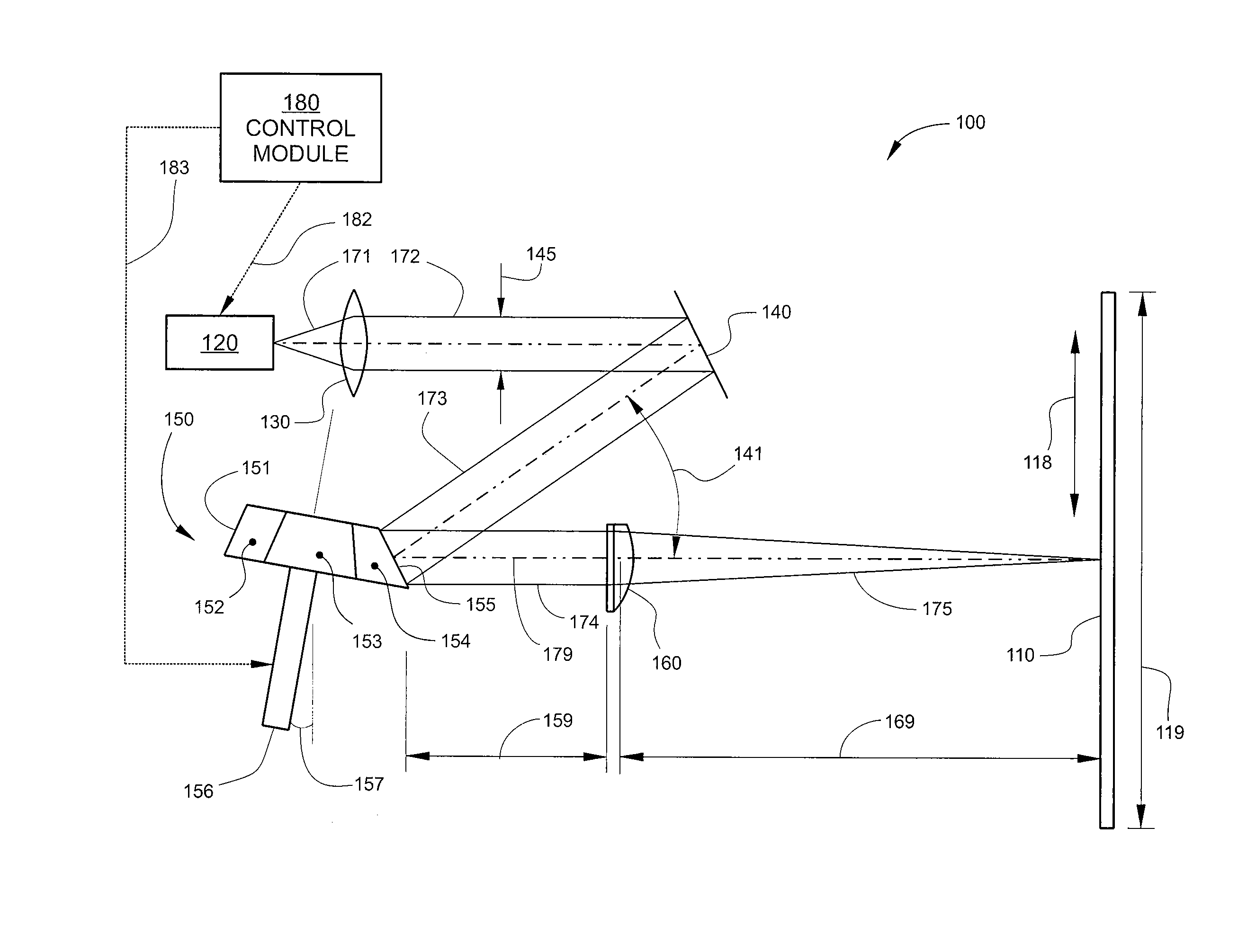
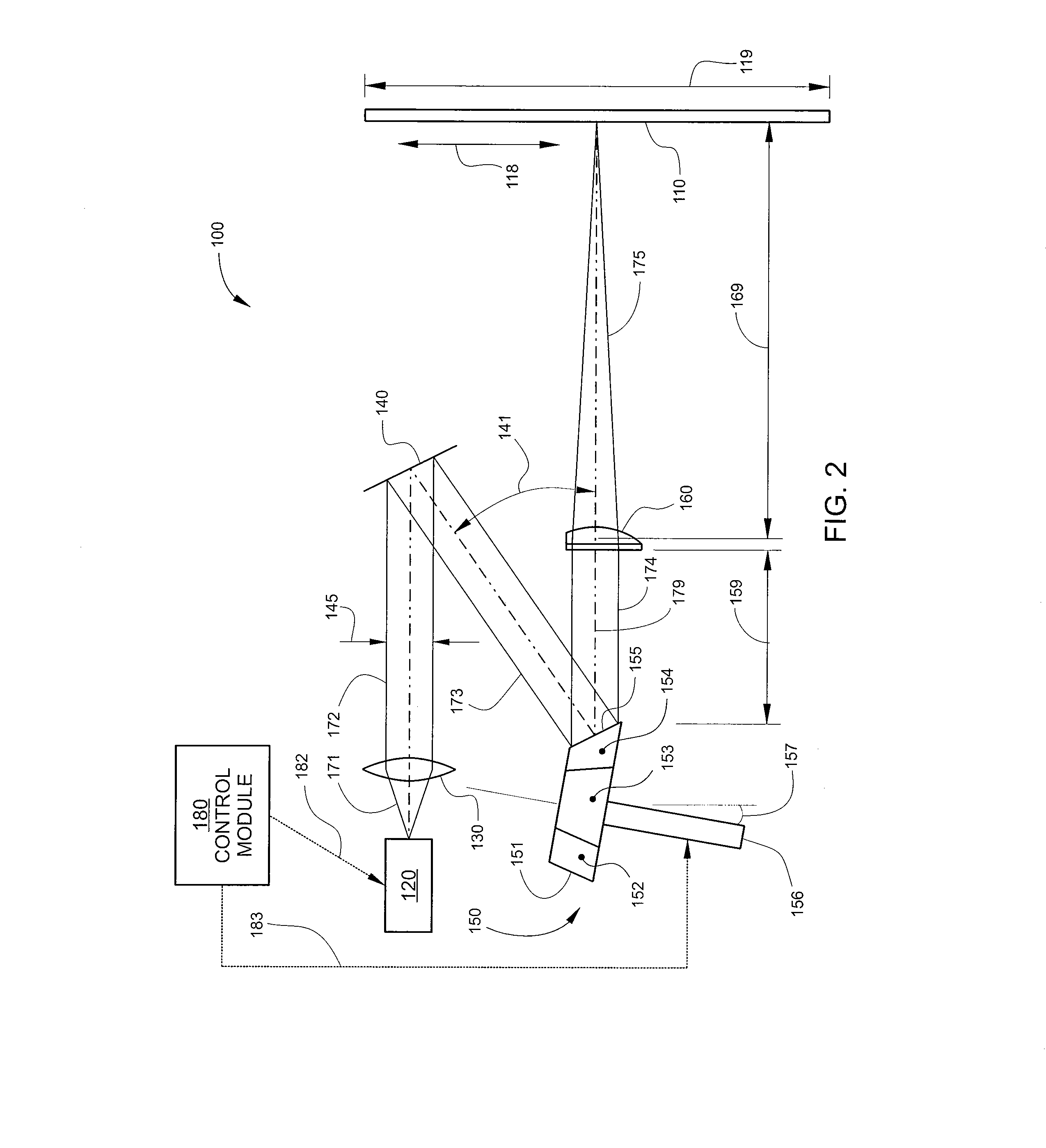
[0023]FIG. 2 is a schematic diagram of a two-dimensional (2-D) scanning system 100 configured according to embodiments of the invention. 2-D scanning system 100 is a system that generates an image on a 2-D imaging surface 110 by scanning a single or multiple light beams across the surface of imaging surface 110 in a 2-D fashion. In some embodiments, 2-D scanning system 100 may be a laser-based display apparatus, such as a laser-phospor display (LPD) that uses a single or multiple lasers for optically exciting light-emitting or fluorescent materials on imaging surface 110 to generate an image. In other embodiments, 2-D scanning system 100 may be an electrostatic image printing machine, in which imaging surface 110 is a surface of a light-sensitive device. In the embodiment illustrated in FIG. 2, 2-D scanning system 100 is configured as an LPD, and includes imaging surface 110, a laser module 120, a collimating lens 130, an approach mirror 140, a raster polygon mirror 150, scan optics...


PUM

PropertyMeasurementUnit
Angleaaaaaaaaaa

Abstract

A 2-D scanning system uses a fast-rotating raster-polygon as a single scanning component to produce straight scan lines over a 2-D image surface. An approach angle of incident light beams to the raster-polygon is selected to minimize pin-cushion distortion of scan lines introduced by polygon scanning on the image surface, and a tilt angle of the rotational axis of the raster-polygon is selected to position said polygon-scanning distortion symmetrically on the image surface. In addition, scan optics are configured to generate a predetermined amount of barrel distortion of scan lines on the image surface to compensate for pin-cushion distortion introduced by polygon scanning.

Description

BACKGROUND OF THE INVENTION[0001]1. Field of the Invention[0002]Embodiments of the present invention relate generally to laser-based image-generating systems and, more specifically, to systems for producing 2-D straight-line scanning on an imaging surface using a raster polygon and a method of forming the same.[0003]2. Description of the Related Art[0004]In laser-based image-generating systems, a rotating polygon mirror is commonly used to scan one or multiple laser beams across an image-generating surface, such as the light-sensitive drum of a laser photo-copier or the phosphor screen of a laser-phosphor display. A rotating polygon mirror is a multi-faceted optical element having a plurality of reflective surfaces. A laser beam incident on one of the reflective surfaces is directed to the image-generating surface, and as the polygon rotates, the incident laser beam sweeps across the image-generating surface, thereby producing one line of an image on the image-generating surface.[00...

Claims


Application Information

Patent Timeline
IPC IPC(8): B41J2/47B23P11/00
CPCG03G15/0409G02B5/09G02B26/101Y10T29/49826H04N3/23H04N9/3129G02B27/0031G02B26/125H04N1/1004H04N1/1048B41J2/471
Inventor BAI, HANXIANGHAJJAR, ROGER A.
Owner PRYSM SYST INC
Learn More