
Stereoscopic 3D Camera

Inactive Publication Date: 2013-03-28
3DIP
View PDF3 Cites 7 Cited by
  • Summary
  • Abstract
  • Description
  • Claims
  • Application Information

AI Technical Summary

Benefits of technology

The present invention is a stereoscopic camera system that is designed to function like the human eye. It uses precise sensor and lens pairs to eliminate unpleasant visual side-effects and requires minimal post-processing image corrections. The camera system is modular in nature, with a detachable mounting system and a wide variety of sensor and lens types that can be easily attached. It also supports a wide variety of sensors and has a unique lens mount that ensures alignment is not compromised when attaching or removing lenses. The camera system has a high-speed recording capability and supports a wide range of sensor resolutions and frame rates. It is equipped with a positioning system and can be set up for remote use. The camera system is designed to be secure and can be controlled by external supervisors. Overall, the invention provides a high-quality stereoscopic camera system with improved image quality and efficiency.

Problems solved by technology

This is clearly too heavy for easy mobile use.
Image sensors on such units are not precisely matched and operate inconsistently causing differences in performance (i.e. differing color balance levels).
Unmatched optical components also tend to cause unpleasant physical side effects for users, such as nausea and headaches.
Current stereoscopic 3D systems lack modular functionality and the optics of a system cannot be changed in the field.
This creates a cumbersome and unwieldy system that is generally unsuitable for many film settings.
Such systems require long setup times between each shoot.
Most systems are not robust and cannot easily retain alignment of sensors and lenses nor are they symmetrical and cannot be used with a Steadicam system.
Existing systems do not support complete 3D meta-data, specifically inter-axial distance and convergence angle.
Existing systems are limited in the types of lenses supported by the systems.
For example, existing systems often do not support wide-angle lenses.
The demand for high resolution systems cannot be adequately met with the current level of technology as most systems cannot support high performance sensors up to 4K.

Method used


Image

  • Stereoscopic 3D Camera
  • Stereoscopic 3D Camera
  • Stereoscopic 3D Camera

Examples


Embodiment Construction

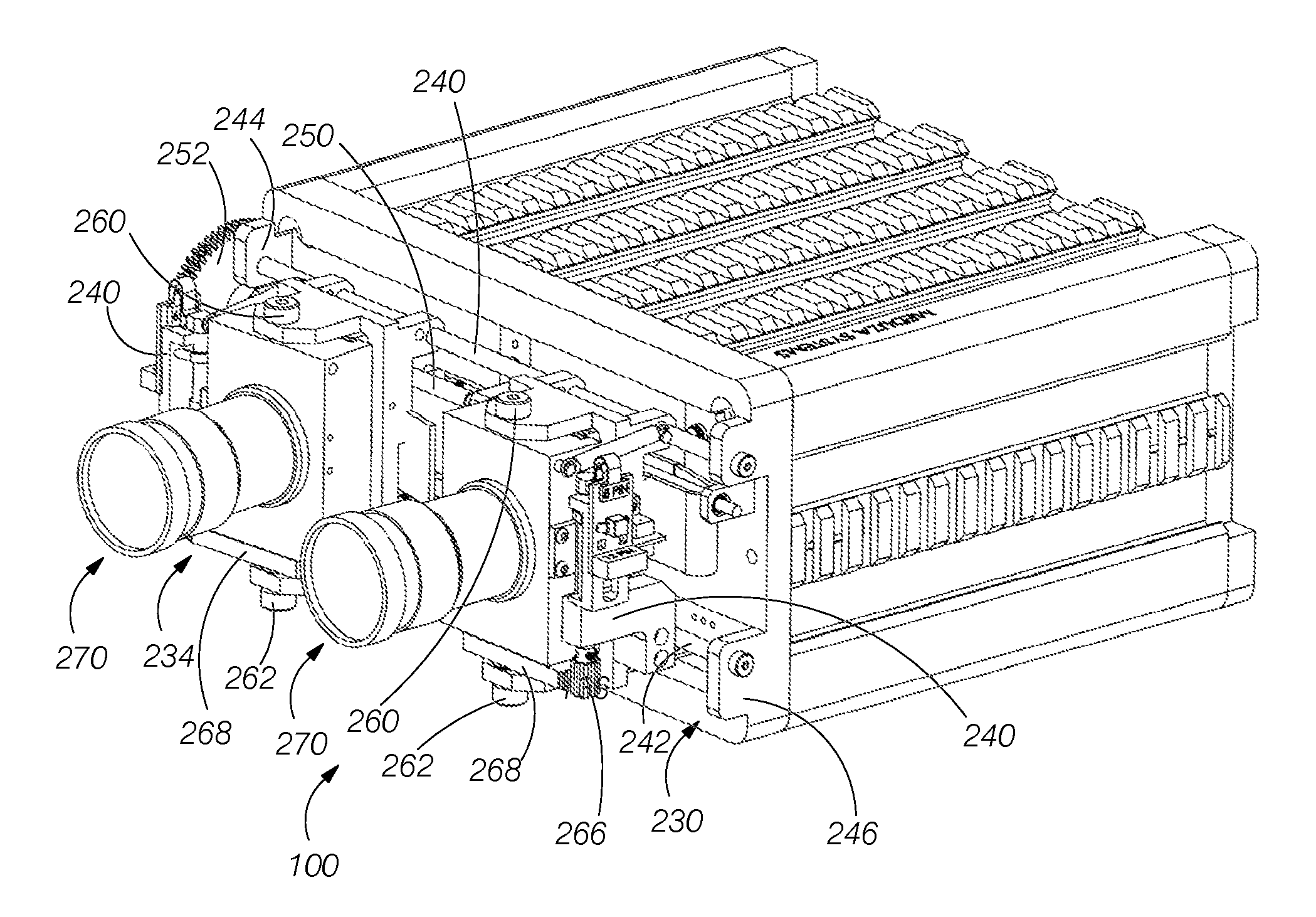
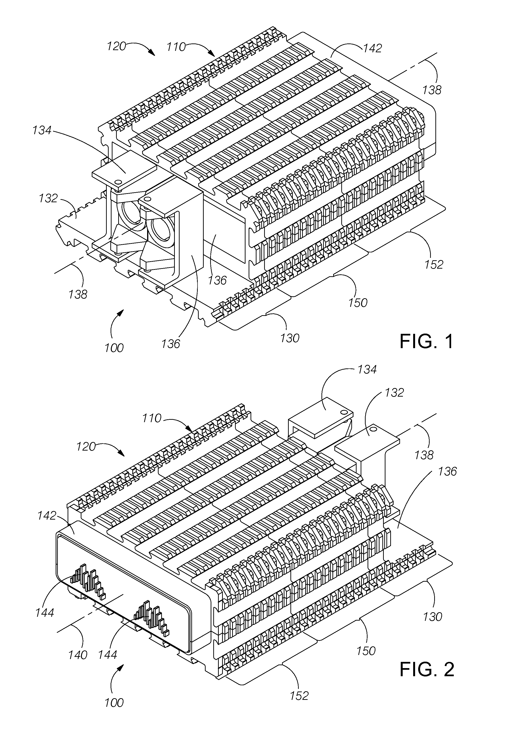
[0035]FIGS. 1 and 2 illustrate front and rear perspective views, respectively, of a 3D camera system 100 that incorporates a universal rail mounting system 110 as part of an enclosure 120 of the 3D camera system. As illustrated, the front of the 3D camera system includes a lens mounting subsystem 130 having an extended lower support platform 132 that supports a first lens assembly 134 and a second lens assembly 136. The two lens assemblies are mounted to a positioning assembly 138 that is controllable to vary the distance between the two lens assemblies about a centerline 140. Each lens assembly is further positionable to vary the angle of the lens assembly with respect to the centerline to adjust the focal point. The lenses within each lens assembly are adjustable with respect to at least the aperture and the focal length. Each lens assembly includes a photodetector array that receives a respective image and generates an electronic representation of the image. An electronics subsys...


PUM


Abstract

A stereoscopic 3D camera that utilizes a single set of electronics to power and control two sensor / lens modules. The camera will be optically designed to mimic the human eye, including the ability to converge upon an object of interest while rotating about the nodal point of the lens / sensor module. The system as a whole will be modular and lightweight, with field changeable lens / sensor assemblies. Camera functions are controlled via multiple remote controls allowing multiple operators to simultaneously control their allocated tasks.

Description

RELATED APPLICATIONS[0001]The present application is a continuation of U.S. patent application Ser. No. 13 / 439,834, filed on Apr. 4, 2012, which claims the benefit of priority under 35 USC §119(e) to U.S. Provisional Application No. 61 / 471,211, filed on Apr. 4, 2011; to U.S. Provisional Application No. 61 / 471,689, filed on Apr. 4, 2011; and to U.S. Provisional Application No. 61 / 472,185, filed on Apr. 5, 2011, which are incorporated herein by reference.BACKGROUND OF THE INVENTION[0002]1. Field of the Invention[0003]The present invention is in the field of software-based design tools for creating integrated circuits having active components operating in the electromagnetic fields of high frequency transmission signals.[0004]2. Description of Related Art[0005]The current level of stereoscopic camera design makes use of two discrete camera systems loosely coupled together to capture pairs of images. Extensive post processing is often required to present the two images to the viewer in ...

Claims


Application Information

Patent Timeline
IPC IPC(8): H04N13/02
CPCH04N13/0239H04N13/0246H04N13/0207H04N2213/001H04N13/0285H04N13/246H04N13/286H04N13/239H04N13/207
Inventor KITZEN, JONATHAN R.WHALEN, MATTHEW STEPHENTHORPE, ROGER THOMAS
Owner 3DIP
Features
  • Generate Ideas
  • Intellectual Property
  • Life Sciences
  • Materials
  • Tech Scout
  • Unparalleled Data Quality
  • Higher Quality Content
  • 60% Fewer Hallucinations
Learn More