Optical image stabilization using tangentially actuated MEMS devices
Active Publication Date: 2013-03-28
DIGITALPTICS MEMS
View PDF3 Cites 44 Cited by
Summary
Abstract
Description
Claims
Application Information
AI Technical Summary
This helps you quickly interpret patents by identifying the three key elements:
Problems solved by technology
Method used
Benefits of technology
[0008]In accordance with the present disclosure, actuator devices for optical elements are provided which are substantially smaller and simpler than prior art actuator mechanis
Problems solved by technology
The reason for this is due in large part to the larger size, complexity and cost of the actuators needed to effect relat
Method used
Image
Click on the blue label to locate the original text in one second.
Reading with bidirectional positioning of images and text.
Examples
Embodiment Construction
[0033]In accordance with the present disclosure, actuator devices for optical elements are provided which are substantially smaller, simpler and less expensive than prior art actuator mechanisms, and which can be reliably implemented in miniature camera systems to achieve, among others, the same advanced features of higher-end camera systems, and in particular, OIS features.
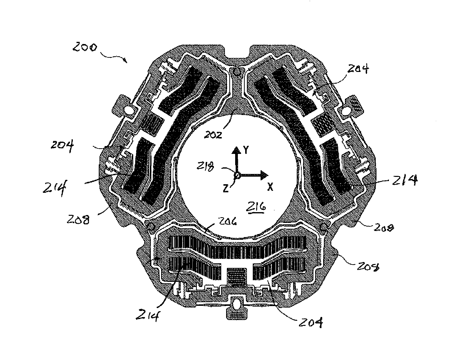
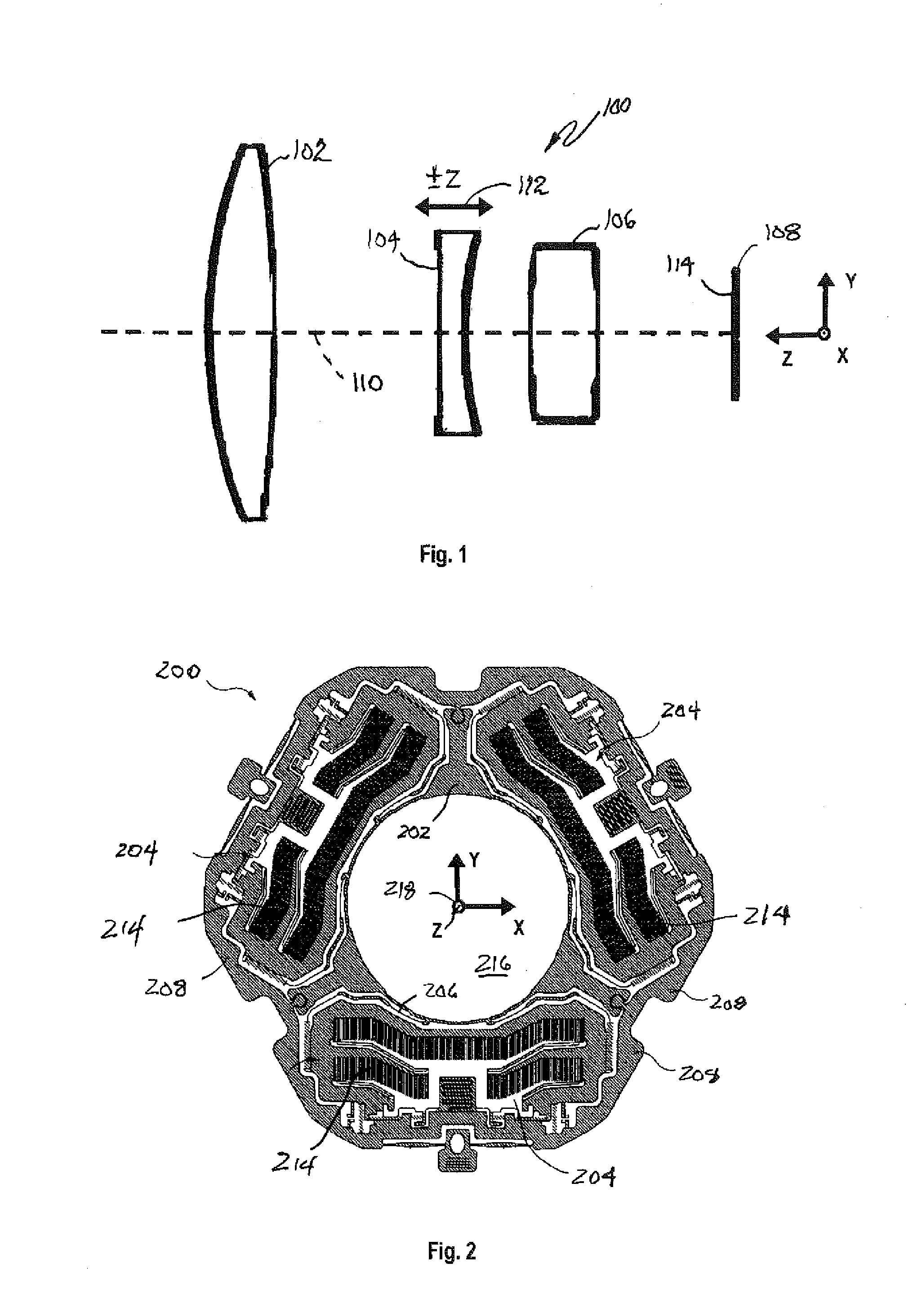
[0034]An example of a miniature digital camera 100 of a type currently found in many stand-alone cameras, cell phones, PDAs, laptop computers, surveillance systems and the like is illustrated in the schematic side elevation view of FIG. 1. The example camera 100 illustrated includes a front-end lens 102, a moveable intermediate lens 104, a back-end lens 106, and a digital imaging sensor 108, such as a CMOS or CCD imaging sensor “chip” or integrated circuit (IC) of a known type, all disposed coaxially with respect to each other along an optical axis 110 of the camera 100. As those of some skill in the art will app...
PUM
Abstract
In one example, an actuator device useful in, e.g., a camera for, e.g., optical image stabilization (OIS), includes a stage resiliently supported for movement within a plane, three or more actuators, each coupled to an outer periphery of the stage and operable to apply a force acting in the plane and tangentially to the stage when actuated, and an outer frame surrounding and supporting the stage and the actuators.
Description
BACKGROUND[0001]1. Technical Field[0002]This disclosure relates, in general, to optical devices and mechanisms, and more particularly, to actuators that are useful in, for example, cameras, particularly miniature cameras and the like, to effect relative movement of optical elements, such as lenses, image sensors and the like, to achieve desirable optical effects, such as, for example, optical image stabilization (OIS).[0003]2. Related Art[0004]Actuators for use in miniature cameras and other optical devices are well known. Such actuators typically comprise voice coils or Lorentz actuators that are used, for example, to move a lens for focusing, zooming, or OIS.[0005]Miniature cameras are frequently used in a variety of different electronic devices. For example, miniature cameras are commonly incorporated in cellular telephones, laptop computers, and surveillance systems. Miniature cameras can also be used to advantage in many other applications, such as colonoscopy, arthroscopy and ...
Claims
Application Information
Patent Timeline
Application Date:The date an application was filed.
Publication Date:The date a patent or application was officially published.
First Publication Date:The earliest publication date of a patent with the same application number.
Issue Date:Publication date of the patent grant document.
PCT Entry Date:The Entry date of PCT National Phase.
Estimated Expiry Date:The statutory expiry date of a patent right according to the Patent Law, and it is the longest term of protection that the patent right can achieve without the termination of the patent right due to other reasons(Term extension factor has been taken into account ).
Invalid Date:Actual expiry date is based on effective date or publication date of legal transaction data of invalid patent.