Motor vehicle part

a technology for motor vehicles and parts, applied in the field of motor vehicle parts, can solve the problems of heavy logistical and stock constraints, label ungluing, and easy slipping of labels, and achieve the effect of facilitating vehicle parts customization and reducing production costs

Active Publication Date: 2013-03-28
VALEO VISION SA
View PDF3 Cites 4 Cited by
  • Summary
  • Abstract
  • Description
  • Claims
  • Application Information

AI Technical Summary

Benefits of technology

[0012]The present invention aims to limit at least some of the drawbacks of the existing solutions. More particularly, it aims to provide a technical solution that facilitates the customization of vehicle parts, such as headlight bezels for example, while reducing the production costs.

Problems solved by technology

These vehicle customization possibilities lead to a very large number of possible combinations, thereby generating heavy logistical and stock constraints.
These solutions present a drawback in terms of reliability.
As it happens, over time, because of the high amplitude thermal cycles and the inevitable ingress of moisture due to the operation of the headlight, the labels have a tendency to become unglued which may prove prejudicial if they block the light source or worse, if they ignite on contact with the latter.
Since these tools represent a significant investment, these solutions are not suited to small production runs and induce significant costs.
The time to produce each bezel and the selling cost are prohibitive.
Thus, the known technical solutions do not therefore allow for a great deal of customization of the vehicles parts, such as the headlight bezels, for small and medium production runs, while keeping costs limited.

Method used


Image

  • Motor vehicle part
  • Motor vehicle part
  • Motor vehicle part

Examples


first embodiment

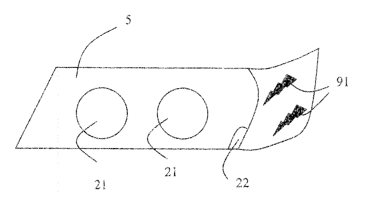
[0086]FIG. 3A illustrates a bezel 5 according to this The bezel 5 comprises two openings 21, 21 for the passage of reflectors. It also comprises a visible portion partly covered with ink or electronic paper to display a pattern 91. The bezel 5 also comprises a connector 22, also called plug, configured to cooperate with a complementary connector also called complementary plug. In this example, the bezel 5 is configured so that, once the optical unit is assembled, the connector 22 is inaccessible from the outside of the optical unit. The programming of the pattern is thus not possible without dismantling the latter.

[0087]According to a second programming mode, the programming of the electronic paper or of the electronic is performed when the subassembly is finalized.

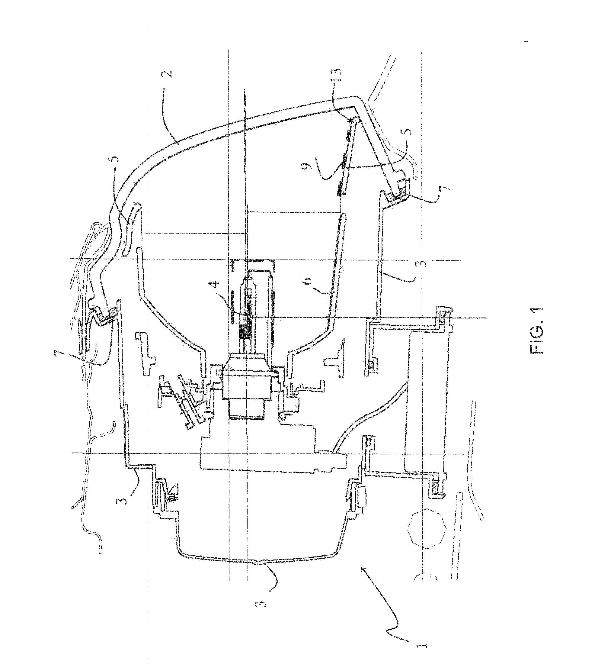
[0088]According to a first option, the connection means are accessible when the subassembly is finalized. For example, in the case of an optical unit 1, the connection means comprise a connector borne by the housing 3 an...

second embodiment

[0096]This second embodiment allows for a very strong customization of the patterns since the programming is performed at the end of the manufacturing of the optical unit 1, even at the end of the manufacturing of the vehicle, or even at any time during the life of the vehicle.

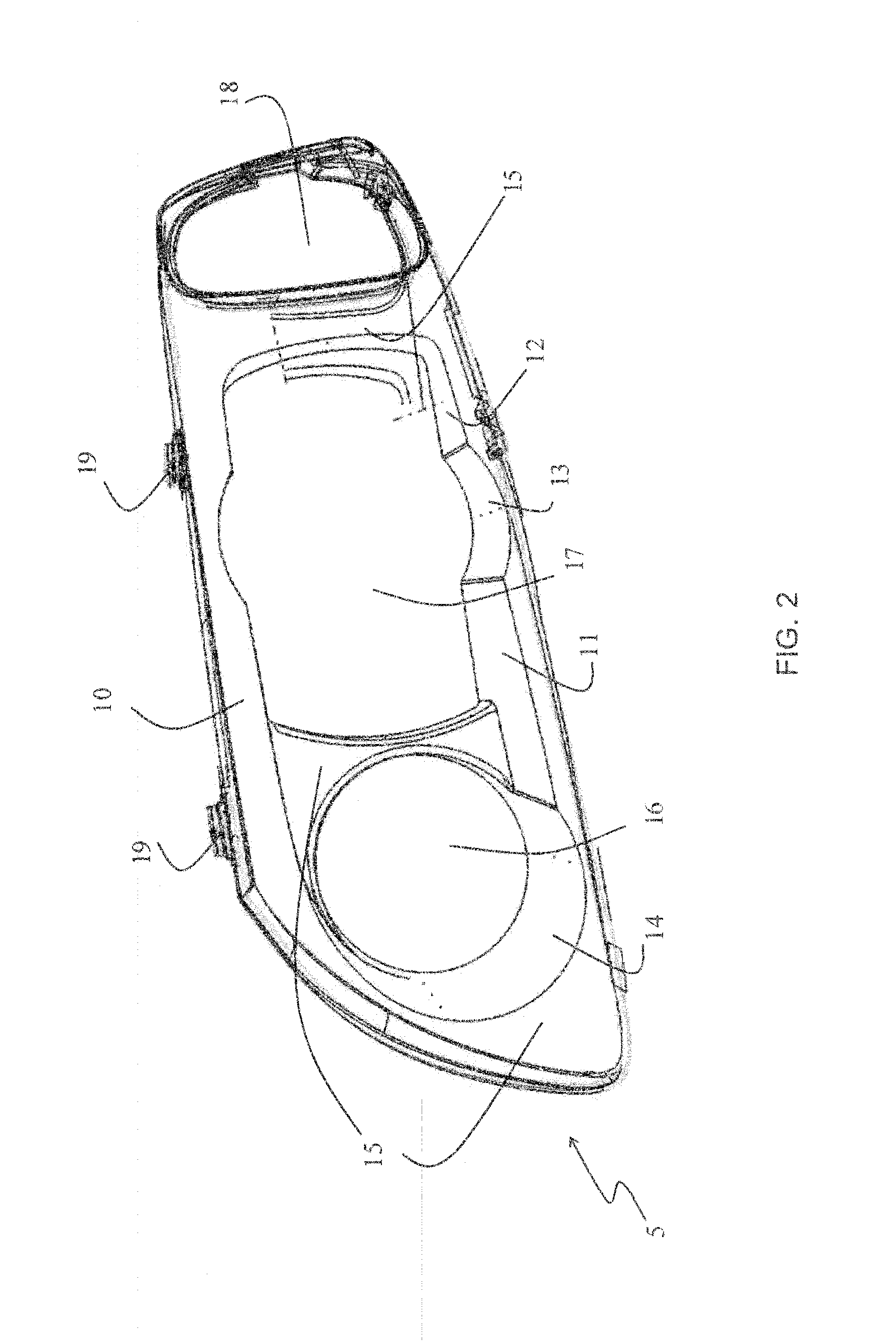
[0097]FIG. 4 illustrates a headlight in which the lens 2 comprises a portion 24 visible from the outside of the optical unit and at least partly covered with electronic ink or paper. Preferably, the electronic ink or paper is deposited on the internal face of the lens 2. The pattern 92 displayed can be a decorative pattern or a regulatory marking. In this example, the bezel 5 also bears one or more patterns 9.

[0098]According to an advantageous embodiment, the part covered with electronic ink or paper or the subassembly incorporating it (optical unit for example) comprises an electronic circuit board for allowing or preventing the modification of the patterns. This can be done according to predefined restrictio...


PUM


Abstract

A motor vehicle part having at least one portion visible from the outside of the part, characterized in that the portion is at least partly covered with an electronic ink suitable for forming a pattern on the portion. A method is also disclosed for manufacturing such a part and a method for manufacturing a subassembly incorporating this part. Another embodiment relates to a set of parts, a marking assembly, an optical unit and a vehicle comprising such a part.

Description

CROSS-REFERENCE TO RELATED APPLICATIONS[0001]This application claims priority to French Application No. 1158649 filed Sep. 27, 2011, which application is incorporated herein by reference and made a part hereof.BACKGROUND OF THE INVENTION[0002]1. Field of the Invention[0003]The present invention relates in particular to a motor vehicle part and to a method for manufacturing this part.[0004]2. Description of the Related Art[0005]The customization of motor vehicles is an aspect which is of increasing importance among vehicle users and potential buyers.[0006]This customization also relates to the esthetic appearance of the vehicles. The configurators proposed on Internet web sites of most motor vehicle manufacturers are good examples. In addition to the choice of vehicle color, it is possible to add chrome plated beads in various positions. It is also possible to differentiate the vehicle through the visual aspect obtained by the daytime light function, this function constituting a true...

Claims


Application Information

Patent Timeline
Patent Type & Authority Applications(United States)
IPC IPC(8): G02B26/00B05D5/12
CPCG09G3/344G09G2380/10F21S48/15G02F1/167F21S48/1233F21S48/1283F21S48/217G09F3/00B60R13/005F21S41/275F21S41/28F21S41/50F21S43/145
Inventor ALBOU, PIERREPUENTE, JEAN-CLAUDE
Owner VALEO VISION SA
Why Eureka
Try Eureka