Linear light source device and planar light source device

a light source device and planar light source technology, applied in the direction of lighting and heating apparatus, instruments, mechanical equipment, etc., can solve the problems of insufficient warp prevention effect, reduced light incidence efficiency degraded adhesive property of light guiding plate, etc., to increase the luminance reduce and reduce the effect of the size of the planar light source devi

Active Publication Date: 2013-03-28
TOYODA GOSEI CO LTD
View PDF6 Cites 13 Cited by
  • Summary
  • Abstract
  • Description
  • Claims
  • Application Information

AI Technical Summary

Benefits of technology

[0014]The purpose of the present invention is to solve the aforementioned problems of the prior art by providing a linear light source device that can be used to form the planar light source device in a small size, and it is possible to efficiently suppress warp of the linear light source device. As another purpose, the present invention provides a planar light source device with the linear light source device arranged on the side surface of the light guiding plate, so that it can suppress warp of the linear light source device, enabling it to realize high luminance.
[0022]According to the present invention, there is no need to use a flexible substrate to connect the linear light source device with the power supply, and it is possible to reduce the size of the planar light source device. In addition, as the central portion in the longitudinal direction of the linear light source device is pressed towards the light guiding plate side so that the external connection terminal and the connector are brought in contact with each other, it is possible to correct the warp of the linear light source device, and it is possible to increase the light incidence efficiency as the light is incident from the linear light source device into the light guiding plate, and it is possible to increase the luminance of the planar light source device.

Problems solved by technology

As a result, its adhesive property on the light guiding plate degrades, and the light incidence efficiency to the light guiding plate decreases.
However, the method described in Patent Reference 2 has insufficient effect in preventing warp.
As can be seen in Patent Reference 3, when a flexible substrate is used to connect with the power supply, and the planar light source device is configured from the linear light source device and a light guiding plate, the planar light source device becomes bulky because there is the flexible substrate portion, which is undesirable.

Method used


Image

  • Linear light source device and planar light source device
  • Linear light source device and planar light source device
  • Linear light source device and planar light source device

Examples


embodiment 1

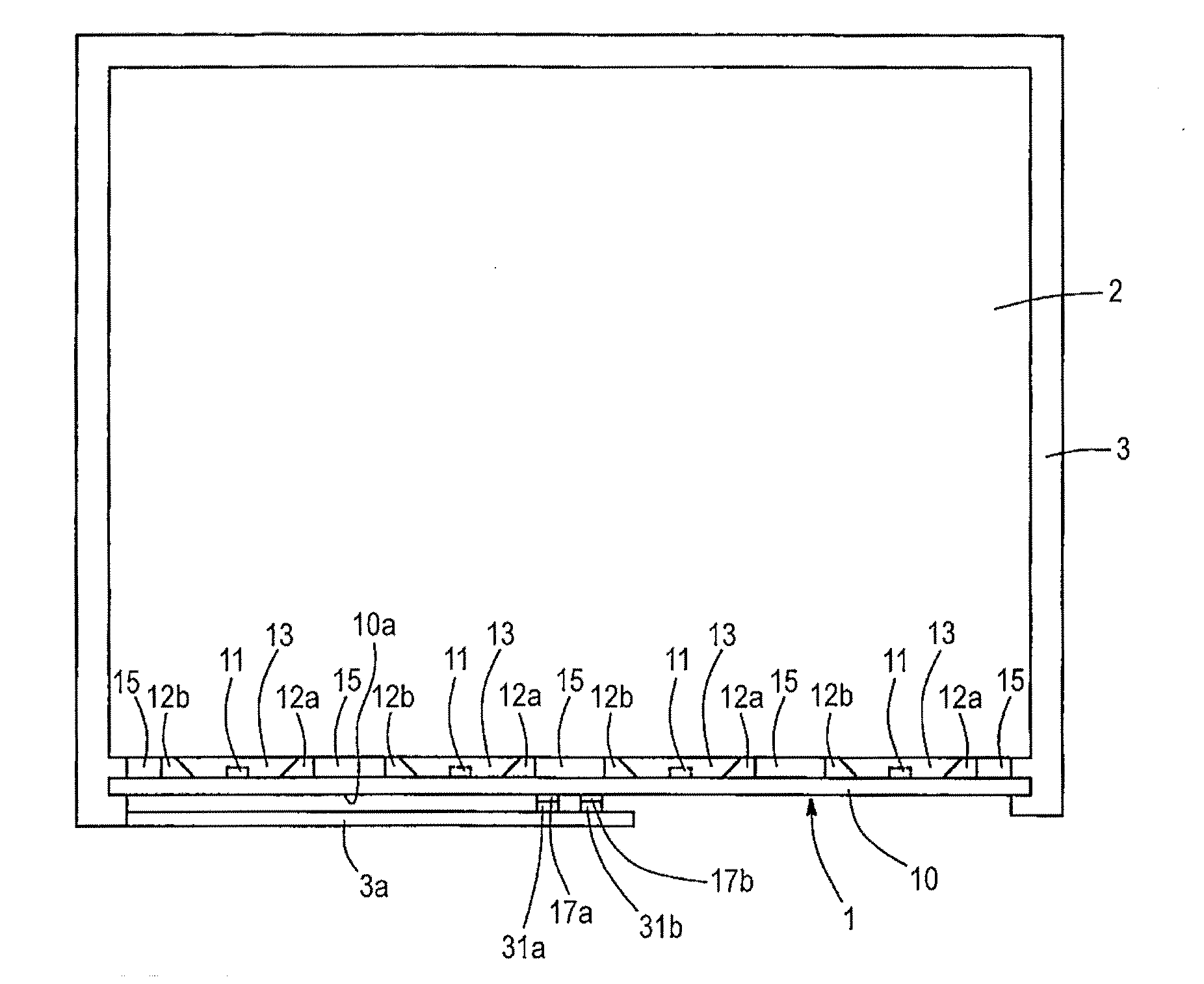
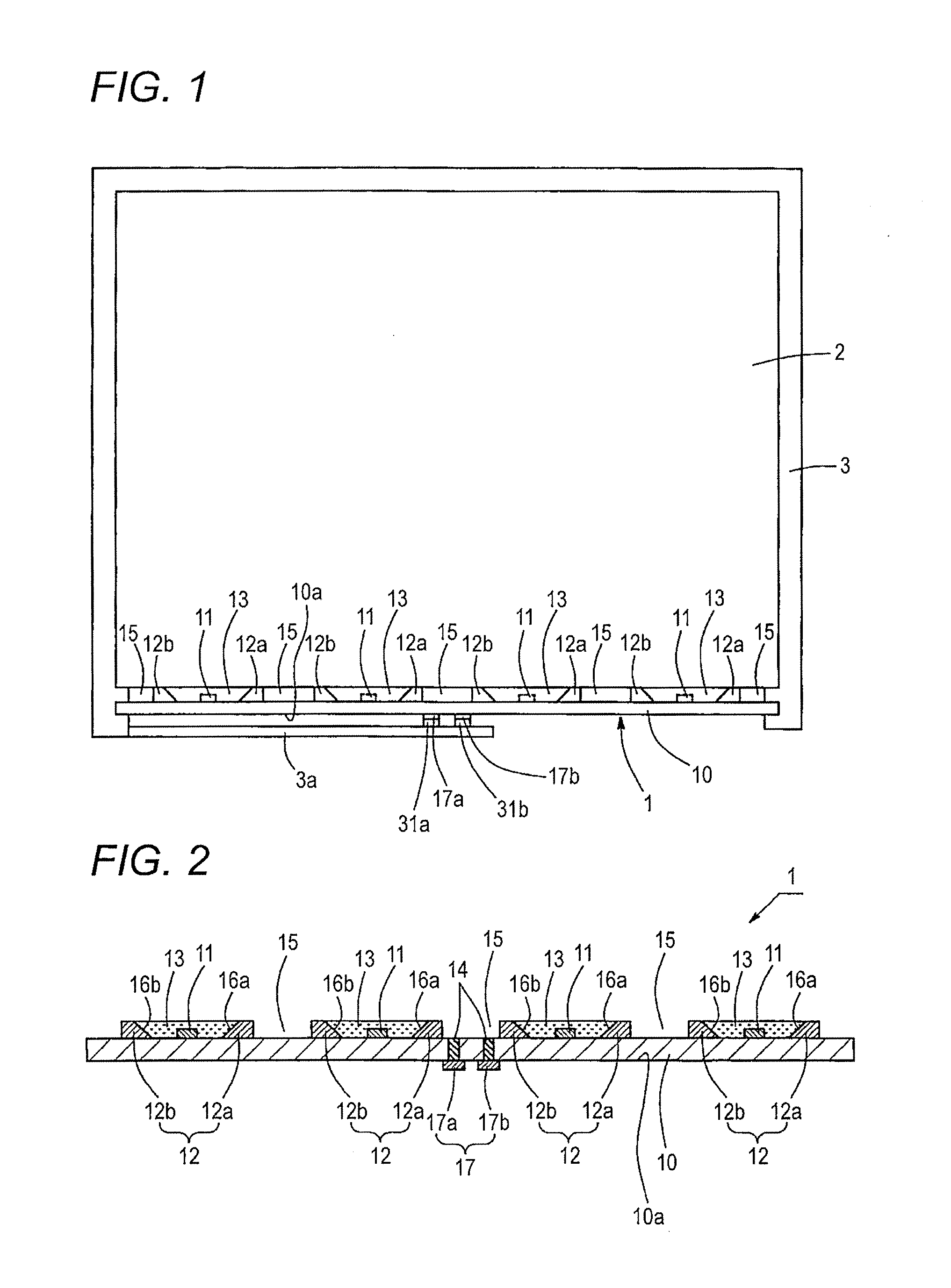
[0028]FIG. 1 is a diagram illustrating the configuration of the planar light source device in Embodiment 1. As shown in FIG. 1, the planar light source device includes a linear light source device 1, a light guiding plate 2, and a frame 3. Here, the linear light source device 1 is arranged such that it has its light emitting direction towards the side surface of the light guiding plate 2, and it is in contact with the side surface of the light guiding plate 2. The frame 3 has a structure that has the light guiding plate 2 and the linear light source device 1 inserted therein so that the position of the linear light source device 1 is anchored with respect to the light guiding plate 2.

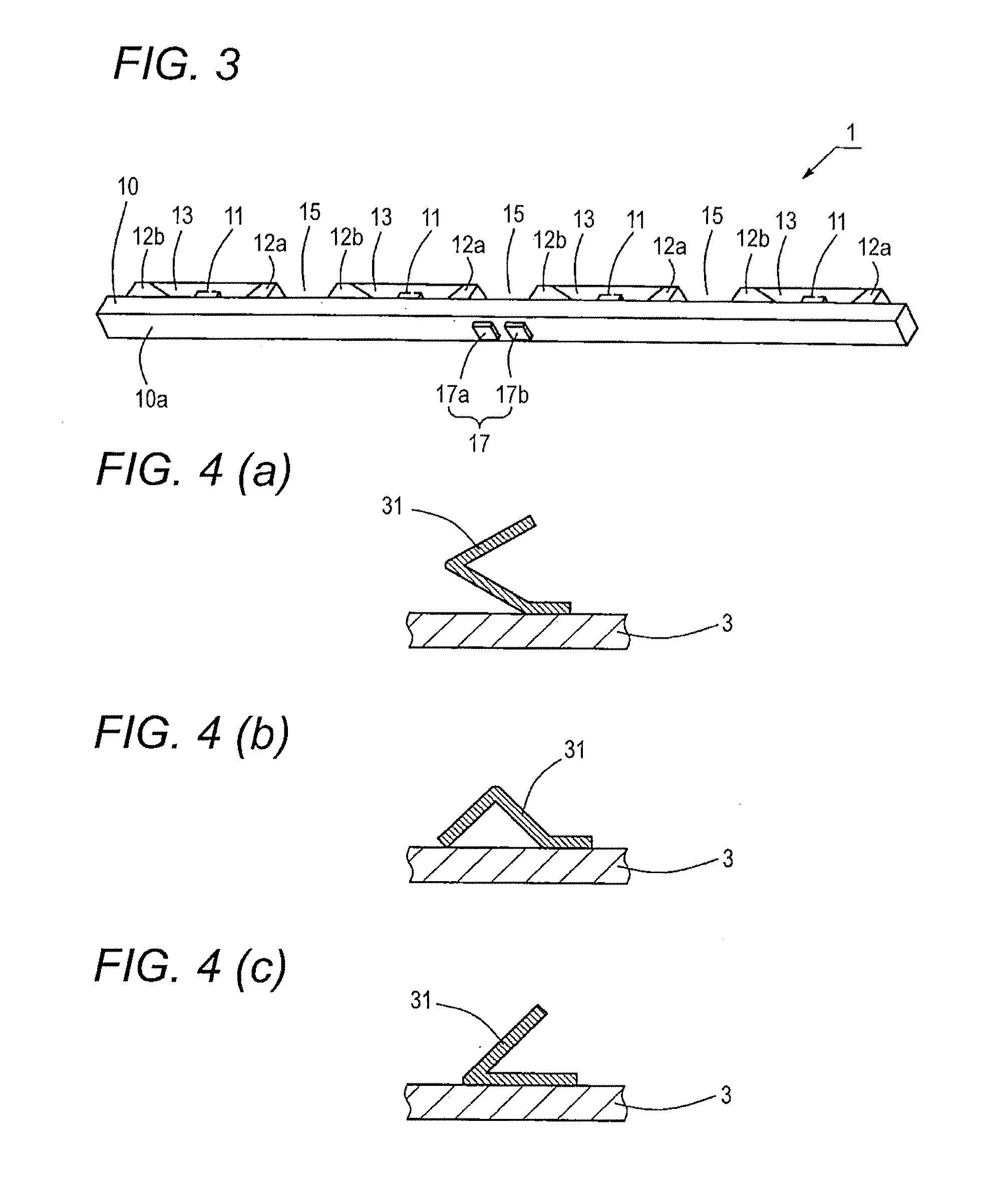
[0029]The configuration of the linear light source device 1 will be explained in the following texts in more detail. FIG. 2 is a cross-sectional view illustrating the configuration of the linear light source device 1. FIG. 3 is a diagram illustrating the linear light source device 1 as viewed in the obl...


PUM


Abstract

A linear light source device comprises a wiring substrate in a rectangular shape and having a wiring pattern formed thereon, a plurality of light emitting elements arranged on the wiring substrate in a longitudinal direction of the wiring substrate and connected with the wiring pattern on the wiring substrate, and a sealing resin that seals the light emitting elements, wherein the linear light source device is to be arranged on a side surface of a light guiding plate to form a planar light source device, and an external connection terminal is arranged on a surface of the wiring substrate that is opposite to a surface of the wiring substrate where the light emitting element are arranged and in a central portion in the longitudinal direction of the wiring substrate, and connected with the wiring pattern.

Description

BACKGROUND OF THE INVENTION[0001]1. Field of the Invention[0002]The present invention relates to a light source device having a plurality of light emitting elements arranged in a linear configuration, and arranged on the side surface of a light guiding plate for making a planar light source device. Also, the present invention relates to the planar light source device.[0003]2. Description of the Related Art[0004]There is a planar light emission light source having a light guiding plate and a linear light source device arranged on the side surface of the light guiding plate (for example, see Patent Reference 1) as the backlight light source of the liquid crystal display panel for use in cell phones or digital cameras, etc.[0005]The linear light source device includes a printed circuit board having a slender rectangular-shaped wiring pattern formed thereon, light emitting elements arranged in plurality separated from each other along the longitudinal direction of the printed circuit bo...

Claims


Application Information

Patent Timeline
Patent Type & Authority Applications(United States)
IPC IPC(8): F21V7/04F21V8/00
CPCG02B6/0068G02B6/0083G02B6/0073
Inventor KOKUBU, HIDEKIITO, YUHKI
Owner TOYODA GOSEI CO LTD
Why Eureka
Try Eureka