
Analog beamformer of ultrasonic diagnosis apparatus

Inactive Publication Date: 2013-03-28
POSTECH ACAD IND FOUND
View PDF8 Cites 26 Cited by
  • Summary
  • Abstract
  • Description
  • Claims
  • Application Information

AI Technical Summary

Benefits of technology

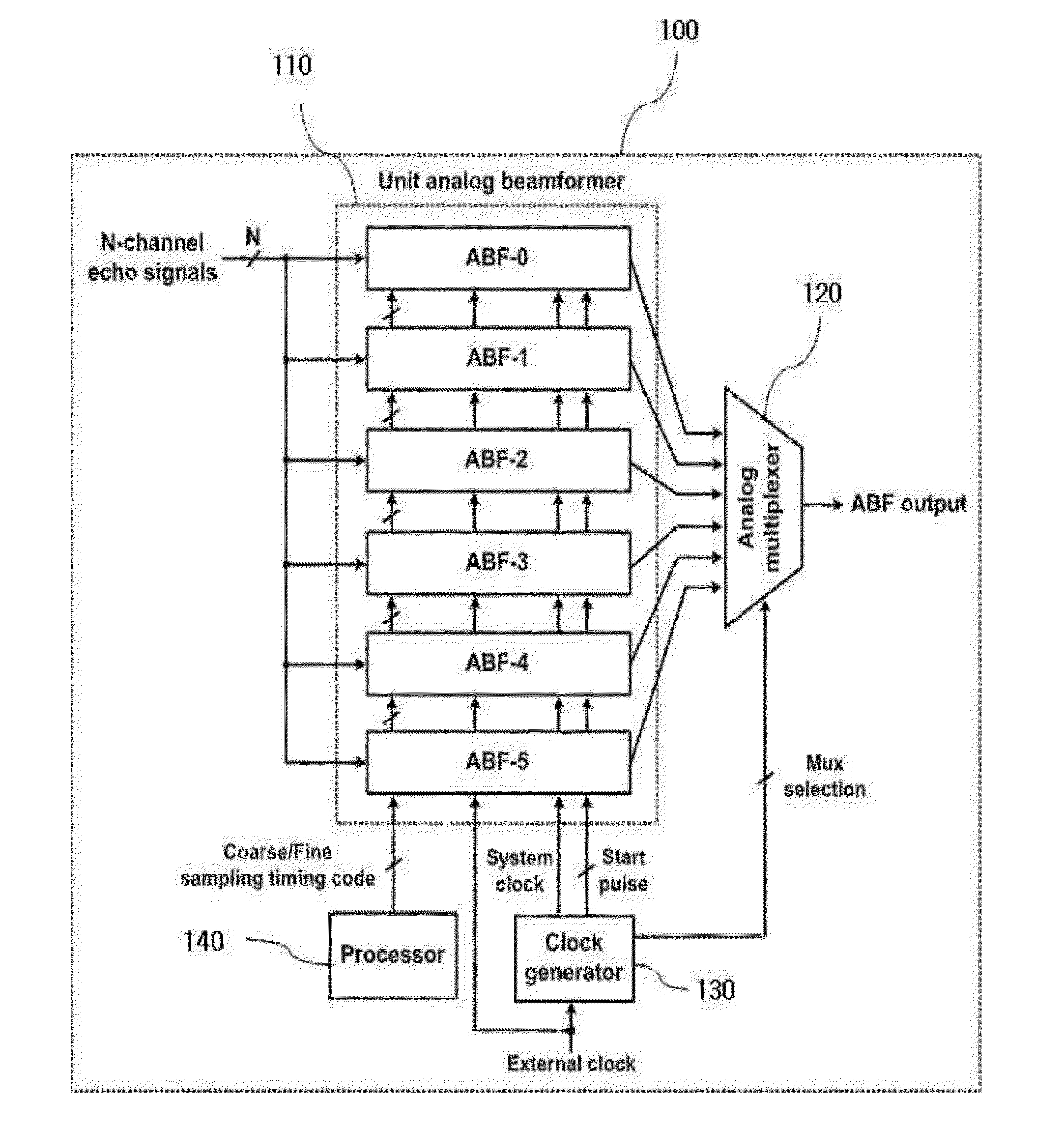
The present invention aims to solve problems in the related art by providing an analog beamformer for ultrasonic diagnosis that operates multiple unit analog beamformers based on a time-interleaving scheme. This reduces the number of op-amplifiers required for the analog beamformer. Additionally, the invention seeks to reduce focusing delay error and widen sampling time control range.

Problems solved by technology

When digital beamforming is used, the hardware size of a beamformer to support such a 2D transducer may be excessively increased.
Therefore, the size and complexity of the hardware used for beamforming may increase to an unmanageable level.
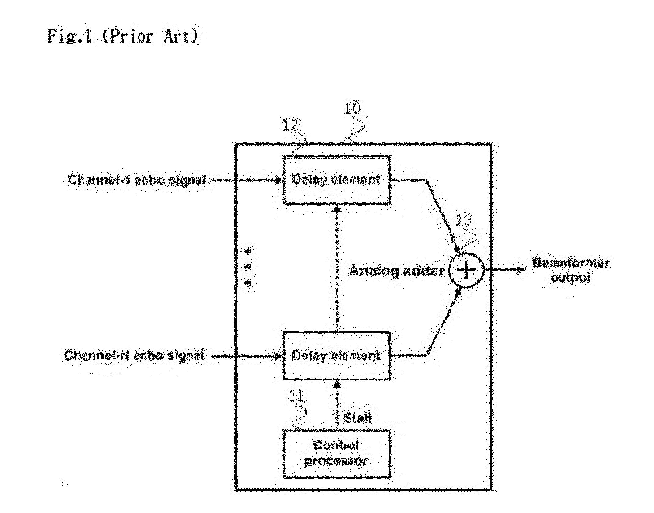
In order for the tapped LC delay line to precisely control delay, the number of taps must be increased, and a multiplexer and a control circuit for controlling the taps become very complex.
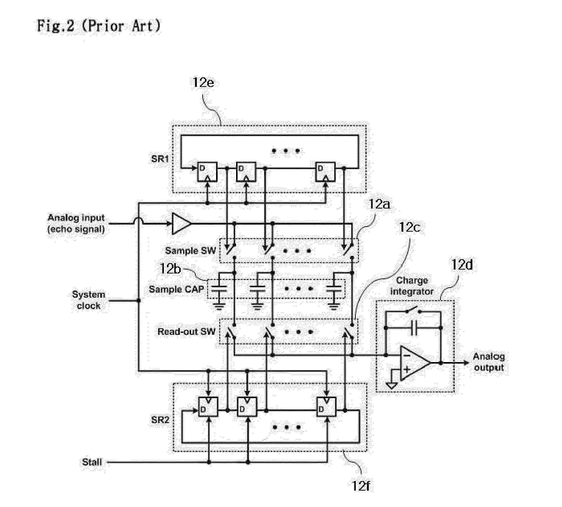
Since the sampling operation is regularly performed at each integer multiple time of the clock signal period TS, a focusing delay error may occur between the focusing delay profile and the regular sampling times.
The focusing delay error caused by the regular sampling operations as illustrated in FIG. 3 may cause incorrect reception beamforming of the beamformer.

Method used


Image

  • Analog beamformer of ultrasonic diagnosis apparatus
  • Analog beamformer of ultrasonic diagnosis apparatus
  • Analog beamformer of ultrasonic diagnosis apparatus

Examples


Embodiment Construction

[0057]Reference will now be made in greater detail to a preferred embodiment of the invention, an example of which is illustrated in the accompanying drawings. Wherever possible, the same reference numerals will be used throughout the drawings and the description to refer to the same or like parts.

[0058]The following embodiments may be implemented by combining components and features of the present invention into a specific form. The respective components or features may be considered to be selective, as long as separate explicit descriptions are not made. The respective components or features may be implemented in a form that is not coupled to other components or features. Furthermore, some components and / or features may be combined to implement the embodiments of the present invention. The sequence of operations described in the embodiments of the present invention may be changed.

[0059]Furthermore, some components or features of any one embodiment may be included in another embodi...


PUM


Abstract

An analog beamformer of an ultrasonic diagnosis apparatus includes: a plurality of unit analog beamformers allocated to two or more focal points, respectively, and configured to beamform signals received from the respective focal points through transducer elements and output the beamformed signals; an analog multiplexer configured to sequentially select the output signals of the unit analog beamformers and generate a final output signal; a clock generator configured to provide a clock signal required for the unit analog beamformers; and a processor configured to provide information on sampling time points of channels, and sequentially operate the unit analog beamformers to perform beamforming according to a time-interleaving scheme.

Description

FIELD OF THE INVENTION[0001]The present invention relates to an ultrasonic diagnosis apparatus, and more particularly, to an analog beamformer of an ultrasonic diagnosis apparatus.DESCRIPTION OF THE RELATED ART[0002]Currently, a digital beamformer is frequently used as a beamformer of a receiver of an ultrasonic diagnosis apparatus.[0003]Since the digital beamformer can use a relatively complex and precise algorithm to implement a beamforming operation in a digital area, the digital beamformer has significantly contributed to improving the quality of an ultrasonic image.[0004]Recently, an interest and demand for ultrasonic 3D images has rapidly increased.[0005]In order to implement a 3D image, a 2D transducer is required. When digital beamforming is used, the hardware size of a beamformer to support such a 2D transducer may be excessively increased.[0006]In particular, the digital beamformer must convert an analog echo signal of each channel into a digital signal, in order to perfor...

Claims


Application Information

Patent Timeline
IPC IPC(8): H04B1/16
CPCG10K11/346A61B8/483G01S7/52026A61B8/00G01N29/24
Inventor UM, JI YONGPARK, HONG JUNEKIM, JAE HWAN
Owner POSTECH ACAD IND FOUND
Learn More