Thermographic Test Method and Testing Device for Carrying Out the Test Method

a testing device and test method technology, applied in the field of thermographic testing method and testing device for carrying out the test method, can solve the problems of false classification of interference as microstructural flaws or defects, increased current density, and increased power loss

Active Publication Date: 2013-03-28
INSTITUT DR FORSTER
View PDF4 Cites 254 Cited by
  • Summary
  • Abstract
  • Description
  • Claims
  • Application Information

AI Technical Summary

Benefits of technology

[0038]These and further features emerge not only from the claims but also from the description and the drawings, where the individual features can be realized in each case by themselves or as a plurality in the form of subcombinations in an embodiment of the invention and in other fields and constitute advantageous and inherently protectable embodiments. Exemplary embodiments are represented in the drawings and are explained in more detail below.

Problems solved by technology

This results in higher current densities, and consequently also greater power losses, at the “constrictions” of the current flow in the region of the defects.
If, however, a defect lies below a minimum defect length but the size of the temperature difference lies above the threshold value, which lies above a maximum size of the temperature difference, such a defect is nevertheless reported as a defect.
Possible sources of interference include local fluctuations in the degree of emission of the surface of the test object, reflections from the surrounding area and circumstances that are generally unavoidable in actual test operation, such as foreign bodies on the surface of the test piece.
Therefore, in spite of all possible measures to reduce the interference amplitude, it cannot be ruled out that interferences are falsely classified as microstructural flaws or defects.

Method used


Image

  • Thermographic Test Method and Testing Device for Carrying Out the Test Method
  • Thermographic Test Method and Testing Device for Carrying Out the Test Method
  • Thermographic Test Method and Testing Device for Carrying Out the Test Method

Examples


Embodiment Construction

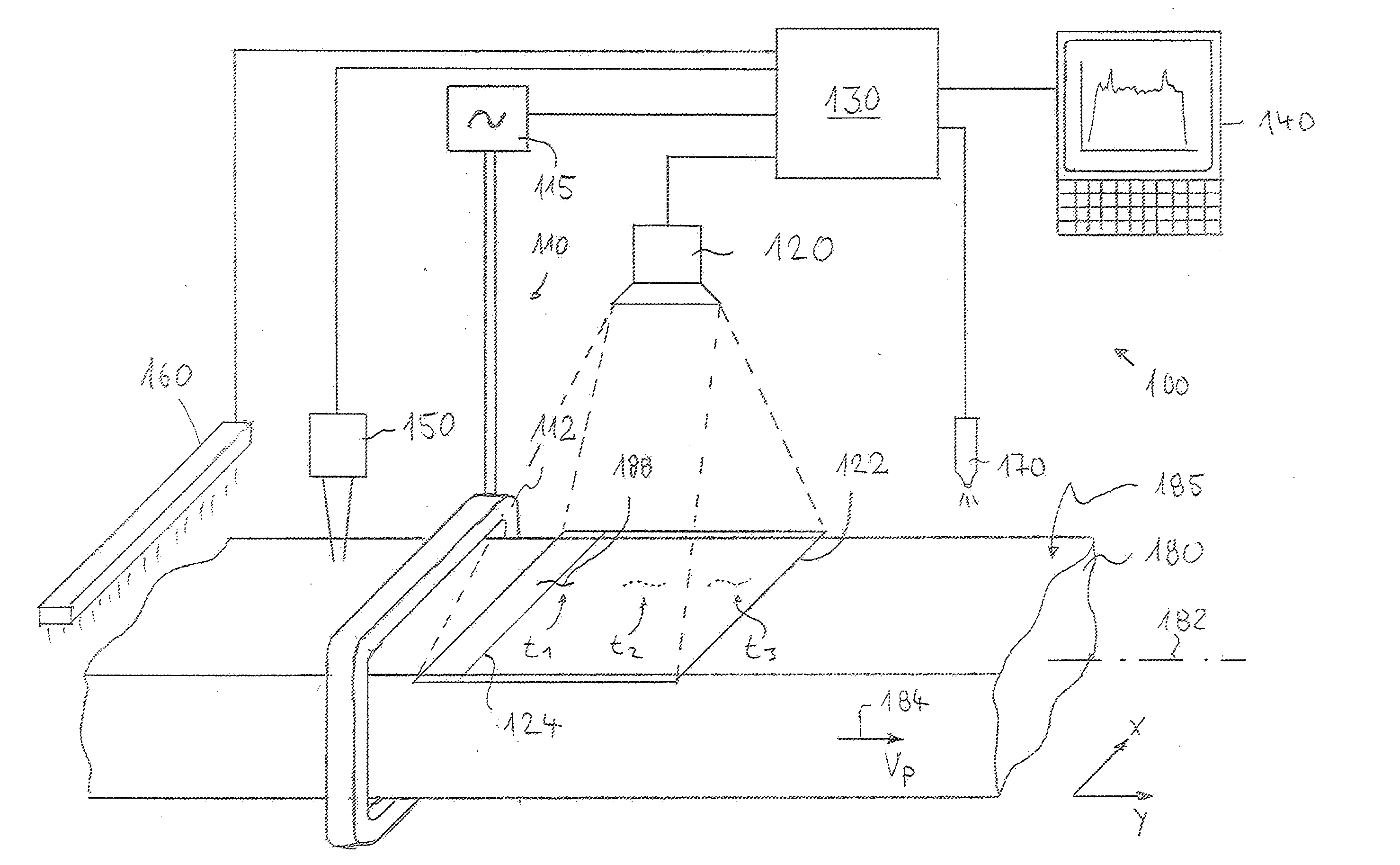
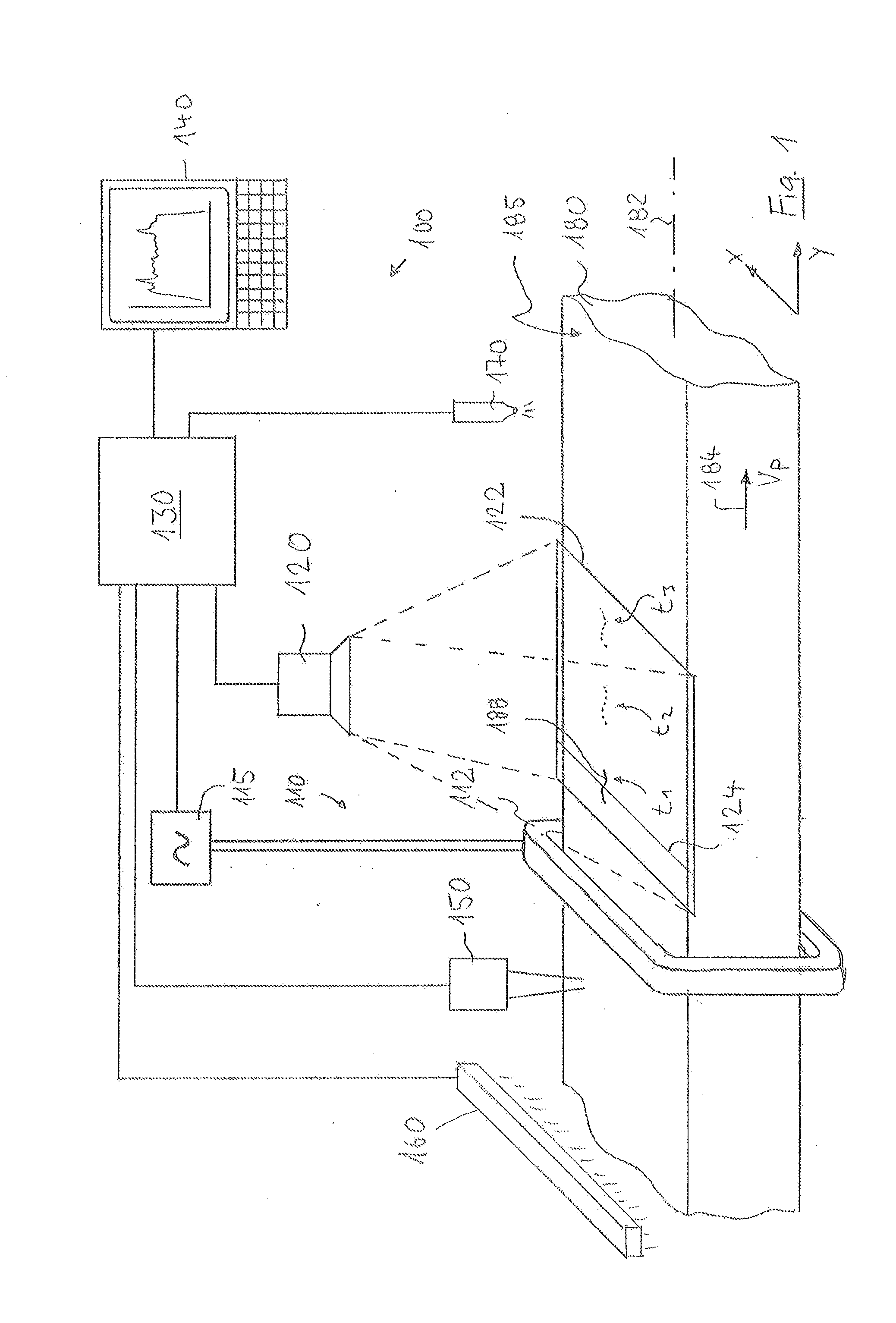
[0045]FIG. 1 shows a schematic representation of an embodiment of a thermographic testing device 100 for testing the complete surface of elongated test objects of electrically conductive material by the run-through method. In the case of the example, the test object 180 is a steel billet with a rectangular cross section, which comes from a rolling device (not represented) and is conveyed with the aid of a conveying device (not represented), for example a roller conveyor, at a largely constant running-through speed vP from the range between about 0.1 m / s and 1.5 m / s in a direction of movement 184 (arrow) extending parallel to its longitudinal axis 182. After the hot rolling, the steel billet does not have a bright surface but a so-called “black” surface, the surface temperature of which typically lies between 0° C. and 50° C. The thermographic testing and the evaluation of the thermographic data thereby recorded are explained on the basis of the testing of the macroscopically level s...


PUM

PropertyMeasurementUnit
temperatureaaaaaaaaaa
speedaaaaaaaaaa
speedaaaaaaaaaa

Abstract

A thermographic test method locally resolves detection and identification of defects near the surface in a test object. A surface area of the test object is heated up. A series of thermographic images following one after another at a time interval is recorded within a heat propagation phase, each image representing a local temperature distribution in a surface region of the test object recorded by the image. Positionally correctly assigned temperature profiles are determined from the images, each positionally correctly assigned temperature profile being assigned to the same measuring region of the test object surface. Variations over time of temperature values are determined from the temperature profiles for a large number of measuring positions of the measuring region. These variations are evaluated on the basis of at least one evaluation criterion indicative of the heat flow in the measuring region.

Description

BACKGROUND OF THE INVENTION[0001]The invention relates to a thermographic test method for the locally resolving detection and identification of defects near the surface in a test object and to a testing device suitable for carrying out the test method.[0002]Semifinished products of electrically conductive material, for example billets, bars, rods, tubes or wires of metallic materials, may serve as starting materials for high-grade end products and often have to meet extremely high quality requirements. The testing for material defects, in particular for defects near the surface such as cracks, voids or other inhomogeneities in the material, forms an important part of the quality control of these products. During this testing, it is generally endeavored to test the surface of the material as completely as possible with high local resolution, which wherever possible is carried out as early as possible in the production chain in order to decide on the basis of the result of the test, d...

Claims


Application Information

Patent Timeline
Patent Type & Authority Applications(United States)
IPC IPC(8): G01N25/72
CPCG01N25/72G06T2207/30136G06T2207/10048G06T7/0004
Inventor TRAXLER, GERHARDPALFINGER, WERNER
Owner INSTITUT DR FORSTER
Why Eureka
Try Eureka