
Offset counterbore for airfoil cooling hole

Active Publication Date: 2013-03-28
GENERAL ELECTRIC CO
View PDF10 Cites 12 Cited by
  • Summary
  • Abstract
  • Description
  • Claims
  • Application Information

AI Technical Summary

Benefits of technology

The technical effects of this patent text include the creation of new features and improvements that are beneficial for those working in this field. These improvements are likely to be revealed through the detailed description and accompanying drawings. Ultimately, the patent aims to protect these new features and improvements from being copied or used without permission.

Problems solved by technology

One issue with the application is such protective coatings, however, is that the spray may plug one or more of the cooling holes.
These masks, however, may be difficult and time consuming to apply and remove.
Although these coating collectors may be effective, typical counterbore designs may break into the casting cavity as airfoil walls become increasingly thinner.

Method used


Image

  • Offset counterbore for airfoil cooling hole
  • Offset counterbore for airfoil cooling hole
  • Offset counterbore for airfoil cooling hole

Examples


Embodiment Construction

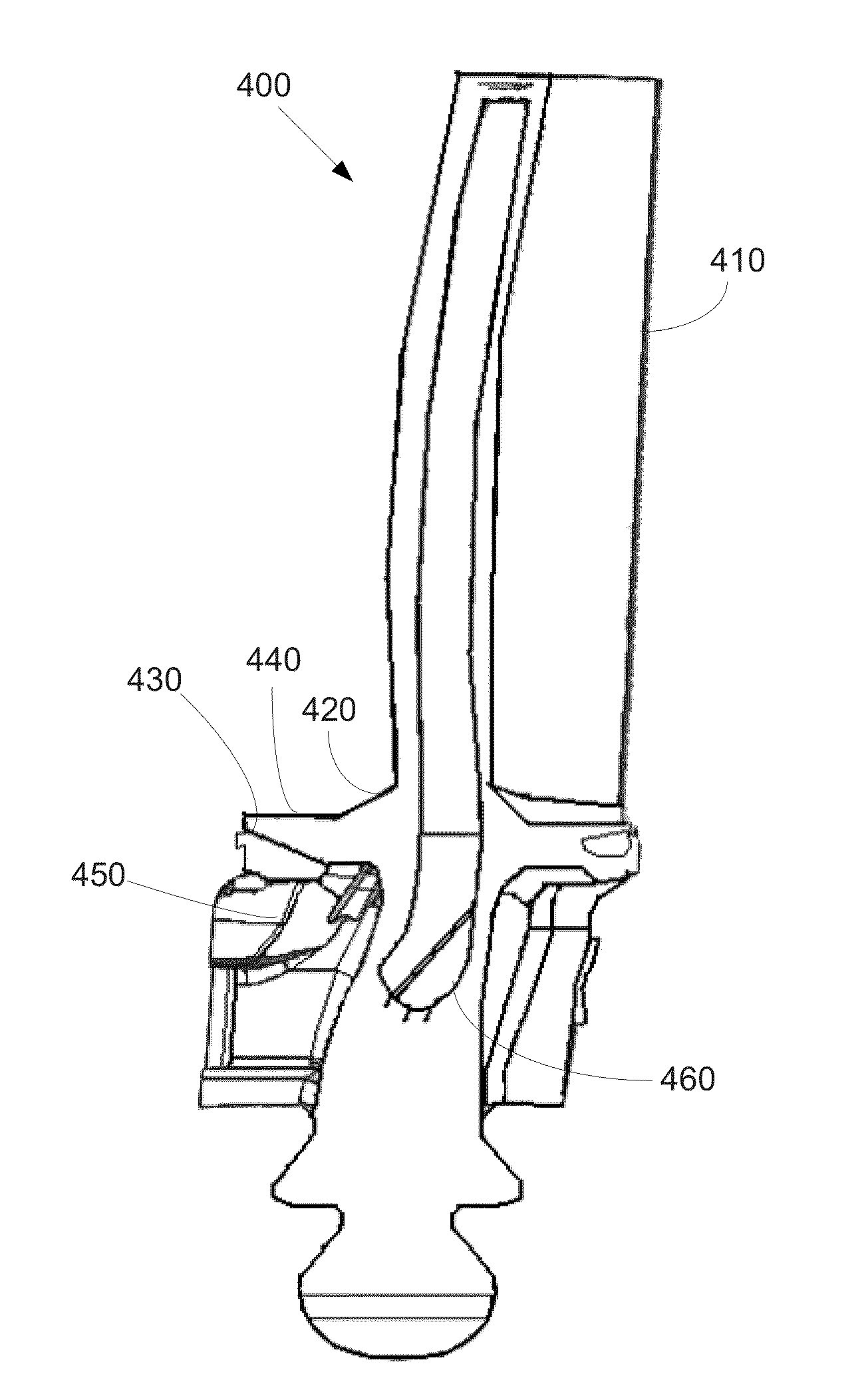
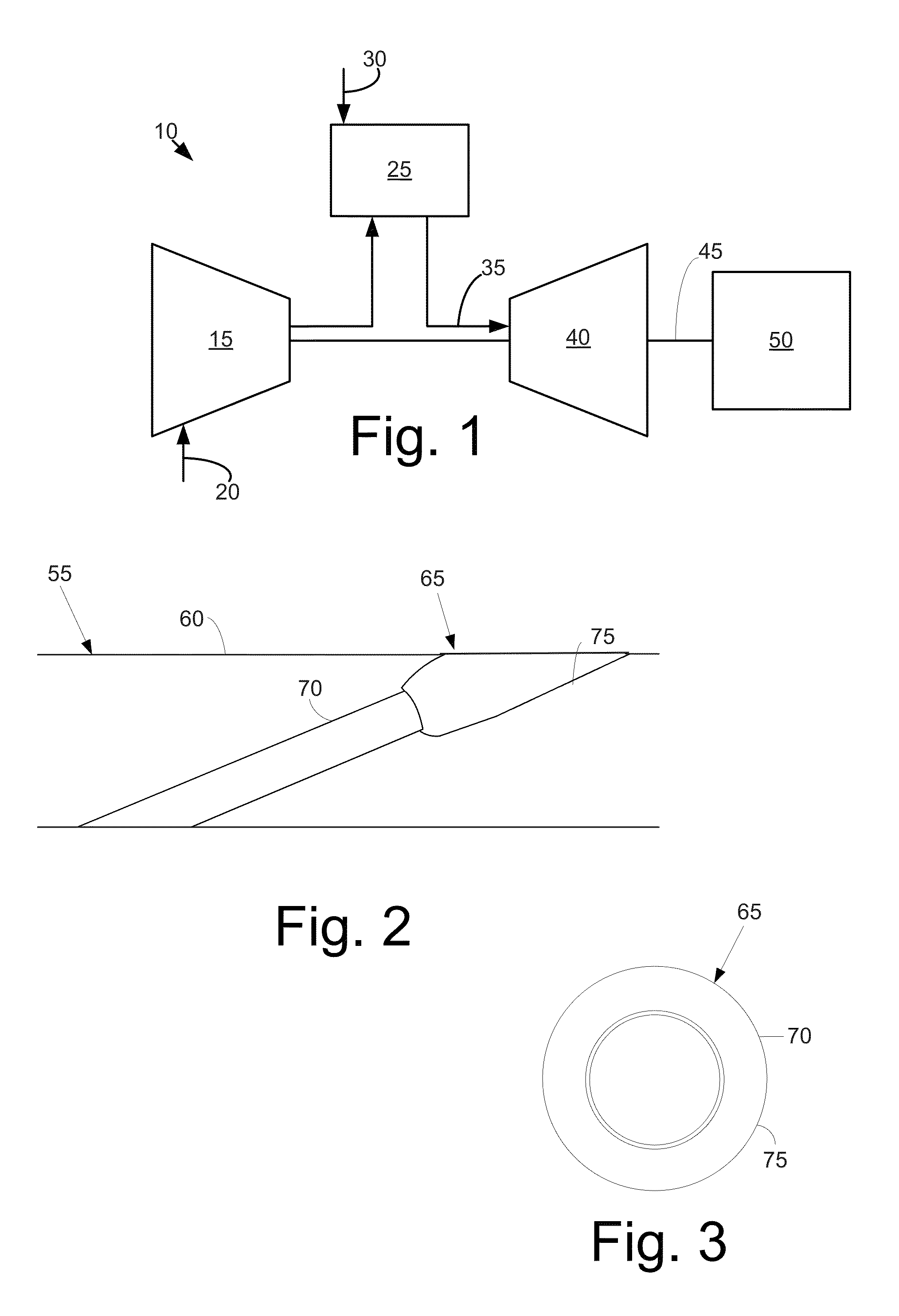
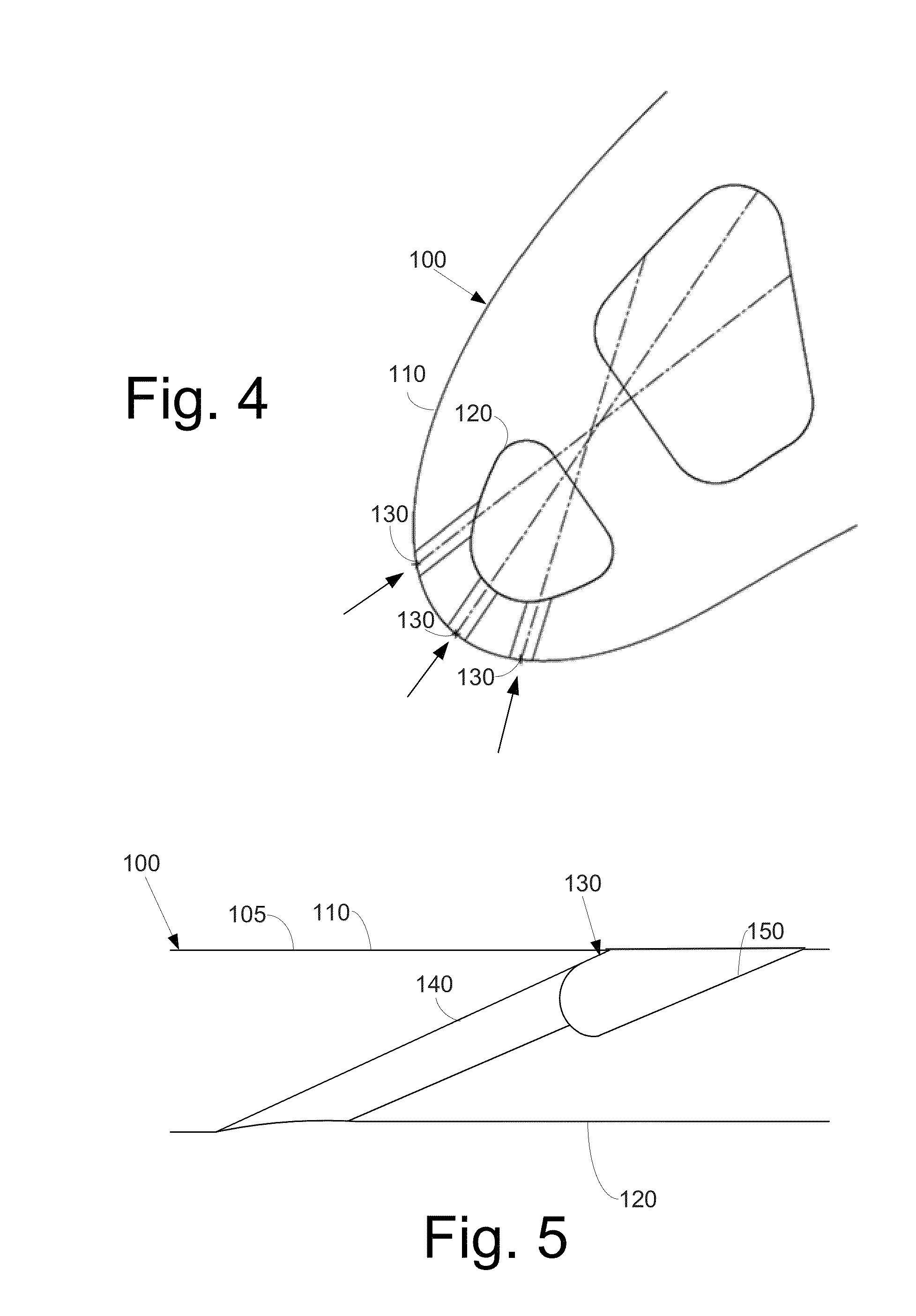
[0020]Referring now to the drawings, in which like numerals refer to like elements throughout the several views, FIG. 1 shows a schematic view of gas turbine engine 10 as may be used herein. The gas turbine engine 10 may include a compressor 15. The compressor 15 compresses an incoming flow of air 20. The compressor 15 delivers the compressed flow of air 20 to a combustor 25. The combustor 25 mixes the compressed flow of air 20 with a pressurized flow of fuel 30 and ignites the mixture to create a flow of combustion gases 35. Although only a single combustor 25 is shown, the gas turbine engine 10 may include any number of combustors 25. The flow of combustion gases 35 is in turn delivered to a turbine 40. The flow of combustion gases 35 drives the turbine 40 so as to produce mechanical work. The mechanical work produced in the turbine 40 drives the compressor 15 via a shaft 45 and an external load 50 such as an electrical generator and the like.

[0021]The gas turbine engine 10 may us...


PUM

PropertyMeasurementUnit
Depthaaaaaaaaaa
Shapeaaaaaaaaaa

Abstract

The present application thus provides an airfoil for use in a turbine. The airfoil may include a wall, an internal cooling plenum, and a cooling hole extending through the wall to the cooling plenum. The cooling hole may include an offset counterbore therein.

Description

TECHNICAL FIELD[0001]The present application and the resultant patent relate generally to gas turbine engines and more particularly relate to offset counterbores for airfoil cooling holes for use as a coating collector while ensuring that a cooling airflow may pass therethrough.BACKGROUND OF THE INVENTION[0002]Airfoils of turbine blades and vanes generally may have a number of cooling holes therein to provide a flow of cooling air to the exterior surfaces of the airfoil and the like. Due to the severe temperatures and conditions in which the turbine airfoils generally operate, protective coatings are often applied to the airfoil and related components after manufacture. Various types of protective coatings may be known. These protective coatings generally are sprayed onto the airfoil and the related components.[0003]One issue with the application is such protective coatings, however, is that the spray may plug one or more of the cooling holes. In order to avoid such, various types o...

Claims


Application Information

Patent Timeline
IPC IPC(8): F01D5/18B23P15/02
CPCF01D5/186F01D5/288F05B2250/70Y10T29/49339F05D2230/11Y10T29/49341F05D2260/202F01D9/065F05D2250/312
Inventor BOYER, BRADLEY TAYLOR
Owner GENERAL ELECTRIC CO
Learn More