Drum lagging material and installation apparatus therefor

a technology of installation apparatus and drum lagging material, which is applied in the direction of mechanical equipment, manufacturing tools, portable power-driven tools, etc., can solve the problems of requiring several days of work and machine downtim

Pending Publication Date: 2013-03-28
ALBANY INT CORP
View PDF7 Cites 7 Cited by
  • Summary
  • Abstract
  • Description
  • Claims
  • Application Information

AI Technical Summary

Benefits of technology

[0009]The lagging substrate can comprise at least one layer selected from the group of woven or non-woven fibers and / or yarns or spiral links. The fibers and / or yarns are selected from the group of: natural fibers and / or yarns and synthetic and / or fibers and / or yarns. The lagging material can also comprise at least two layers. For example, the lagging material can include a woven substrate layer and a fibrous batt material layer, the batt material being manufactured and applied by techniques known to ordinarily skilled artisans such as carding and needling respectively. The lagging material is manufactured such that it is stable in the cross-machine direction (CD). The cross-machine direction (CD) width of a drum of a corrugator machine is typically up to 5 meters or more. The lagging material is also extensible to a degree in the machine direction (MD) along the drum circumference such that it can be stretched sufficiently along the drum surface so as to be seamed on the drum surface yet also maintain that total length over the service life of the lagging material.

Problems solved by technology

In most cases, this requires several days of work and machine downtime.

Method used


Image

  • Drum lagging material and installation apparatus therefor
  • Drum lagging material and installation apparatus therefor
  • Drum lagging material and installation apparatus therefor

Examples


Embodiment Construction

[0022]Initially, although embodiments are disclosed in the context of a drive drum in a corrugator machine, ordinarily skilled artisans will appreciate that the disclosed embodiments of the lagging material and installation device have application to other drive roll covers or other industrial machines that include drive drums, such as papermaking machines and nonwovens manufacturing machinery.

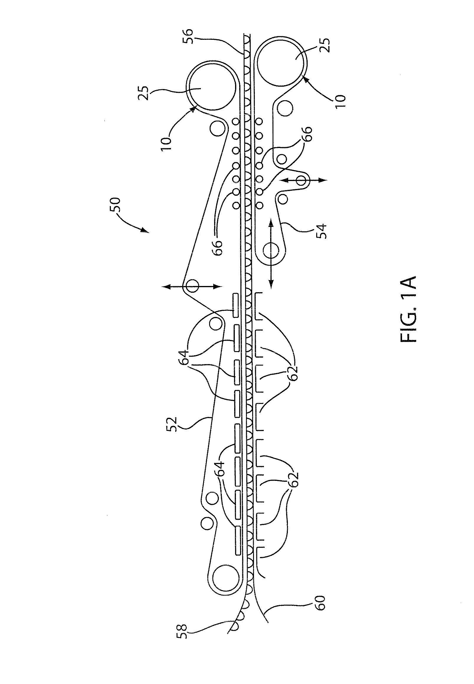
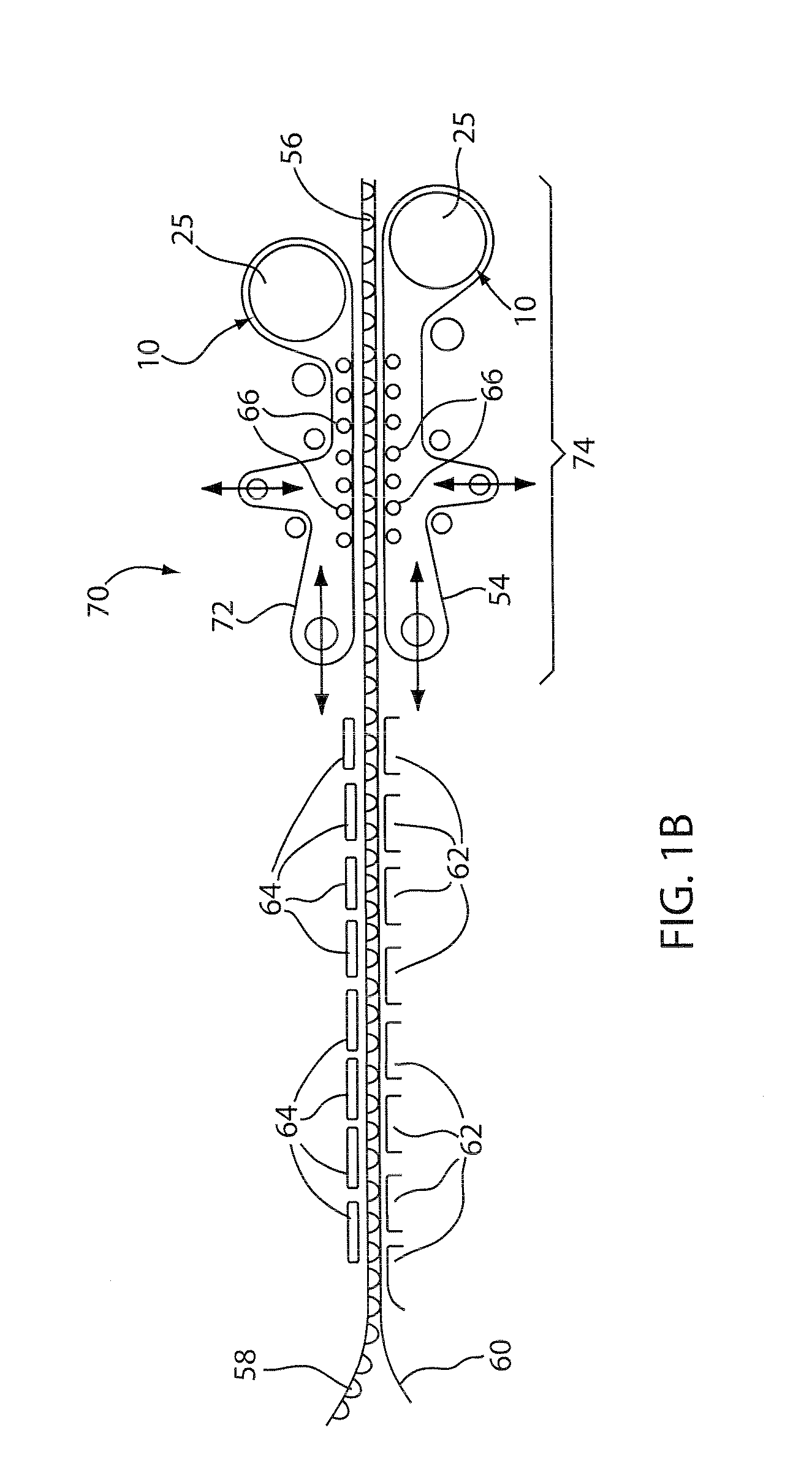
[0023]FIGS. 1A and 1B are schematic views of a typical belted section of a corrugator machine. A corrugator machine 50 in FIG. 1A has an upper corrugator belt 52 and a lower corrugator belt 54 which together support and pull a corrugated paper product 56 therethrough. After passing over hot plates 62, the upper and lower belts 52, 54 together pull the corrugated paper product 56 between them, maintaining the speed of the operation and cooling the paper product 56. Weighted rollers 66 apply pressure from within the endless loops formed by belt 52 and belt 54 toward one another, so that corrugat...


PUM

PropertyMeasurementUnit
thicknessaaaaaaaaaa
thicknessaaaaaaaaaa
thicknessaaaaaaaaaa

Abstract

Disclosed are lagging materials for use on a driven cylindrical pulley or drum for an industrial machine. A lagging material can comprise a seaming element along the cross-machine direction (CD) of each of the opposing ends of the lagging material for forming a seam for seaming opposing ends of a lagging material when brought together. A lagging material can also comprise coatings that increase the Coefficient of Friction of a lagging material when the lagging material is installed onto the drum such that no additional adhesive is required to keep the lagging on the drum circumference when in operation. Also described is an apparatus for installing an on machine seamable lagging including at least two opposed elongate members, such that when the elongate members are drawn together, the lagging material is stretched into a seamable position to be installed on the drum.

Description

CROSS REFERENCE TO RELATED APPLICATIONS[0001]This application claims priority to pending U.S. provisional patent application No. 61 / 538,470, filed Sep. 23, 2011 and to pending U.S. provisional patent application No. 61 / 542,657, filed Oct. 3, 2011, each entitled “DRUM LAGGING MATERIAL AND INSTALLATION APPARATUS THEREFOR,” and the entirety of each of which is incorporated herein by reference.BACKGROUND OF THE INVENTION[0002]The manufacture of corrugated paper board, or box board, on corrugator machines is well-known in the art. The manufacture of corrugated paper board, or box board, on corrugator machines is well-known in the art. An exemplary description of corrugator machines and their use can be found in U.S. Pat. No. 6,276,420, the entirety of which incorporated by reference hereby. In the manufacture of corrugated paper board, a so-called core paper is heated by steam, which makes it more pliable, and is then fed into a nip formed between a pair of toothed rollers whose teeth me...

Claims


Application Information

Patent Timeline
Patent Type & Authority Applications(United States)
IPC IPC(8): B05C11/00B23P19/00B23P11/00
CPCB31F1/30F16G3/16Y10T29/49826Y10T29/53F16C2223/32
Inventor FARRELL, DONALD J.PINSON, CHARLES L.RACZKOWSKI, KAZ P.
Owner ALBANY INT CORP
Why Eureka
Try Eureka