
Flow Directional Infusion Device

a technology of infusion device and flow direction, which is applied in the direction of blood vessel filter, catheter, other medical devices, etc., to achieve the effect of reducing the diameter of the vessel

Active Publication Date: 2013-03-28
TRISALUS LIFE SCI INC
View PDF7 Cites 18 Cited by
  • Summary
  • Abstract
  • Description
  • Claims
  • Application Information

AI Technical Summary

Benefits of technology

The patent describes a device that helps direct the transfer of embolic agents from a catheter into an aneurysm during a minimally invasive procedure. The device includes a filter valve made up of first filaments that are secured at the distal end of a catheter and at a separate location on the distal end of another catheter. This allows for the creation of a tubular form of the filter valve that can be directed toward the aneurysm during the procedure. The filter valve is designed to be permeable to the embolic agent, allowing it to flow from the catheter and enter the aneurysm. A smaller catheter can also be used to inject the embolic agent through the filter valve. The device also helps prevent any embolic agent from flowing back into the blood vessel during the procedure. Overall, this device improves the accuracy and safety of embolic agent transfer during minimally invasive procedures.

Problems solved by technology

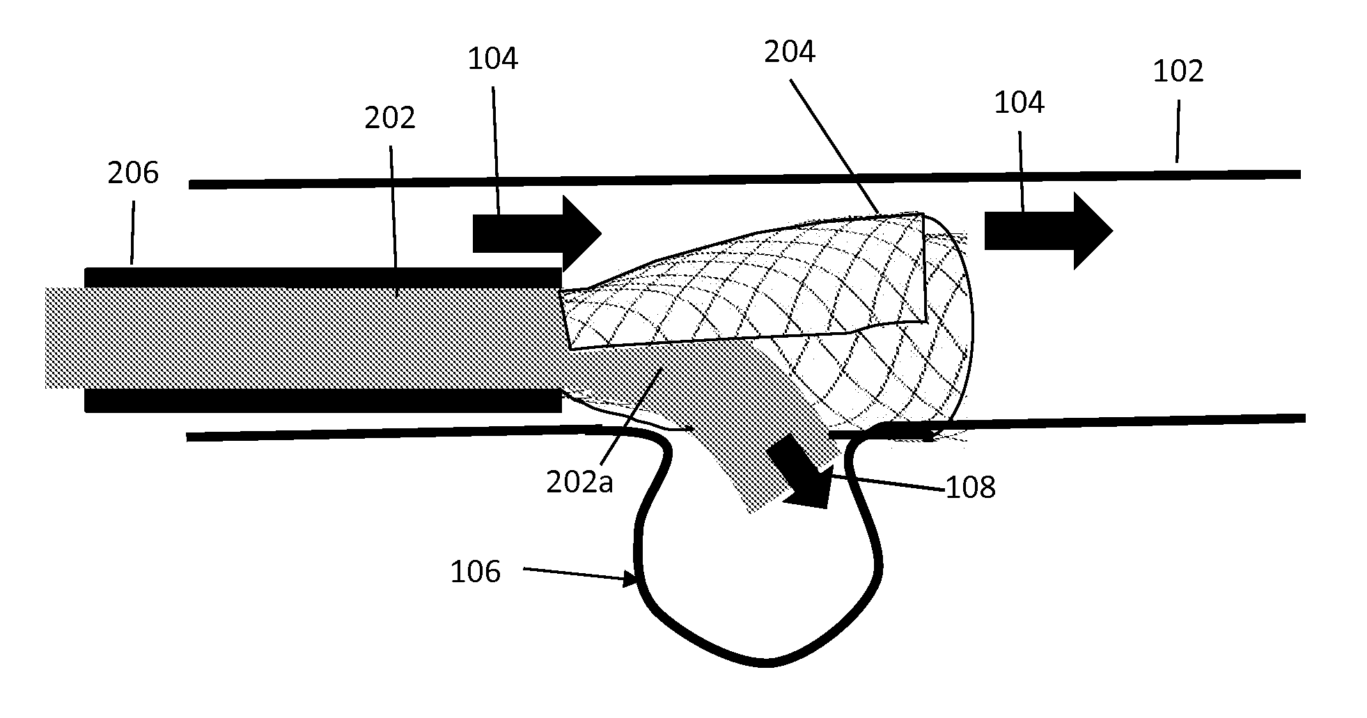
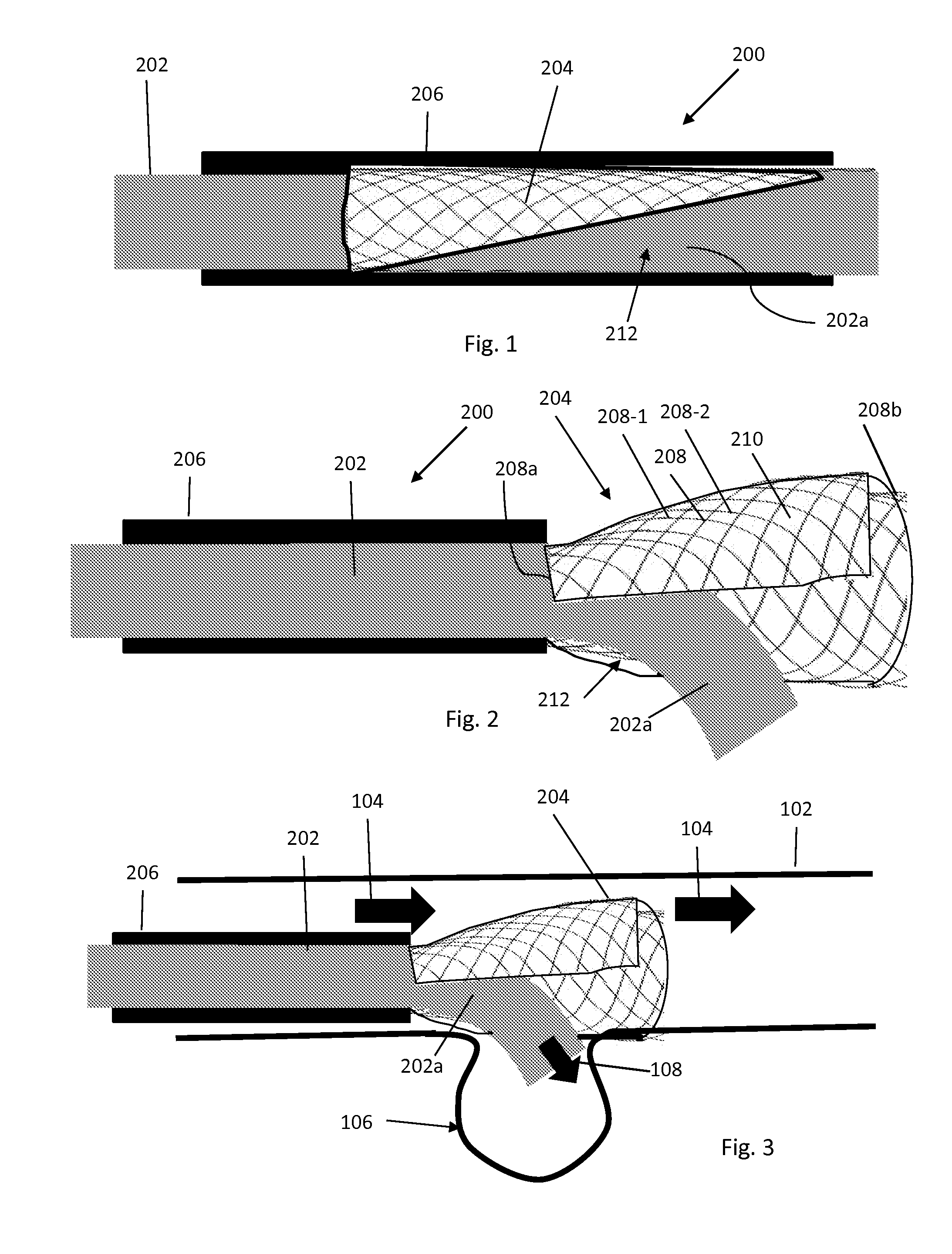
In addition, the filter valve permits and directs blood flow within the blood vessel about the aneurysm during the treatment without obstructing the vessel and without allowing retrograde flow of the embolic agent in the vessel upstream of the aneurysm.

Method used


Image

  • Flow Directional Infusion Device
  • Flow Directional Infusion Device
  • Flow Directional Infusion Device

Examples


second embodiment

[0059]Turning now to FIGS. 7 through 9, an infusion device 300 is shown. The device 300 includes a catheter 302, a filter valve 304, and an outer catheter or sleeve 306 displaceable relative to the catheter 302 and filter valve 304. The filter valve 304 is secured to the distal end of the catheter 302, preferably with no portion of the catheter extending through the filter valve. The filter valve 304 is not necessarily provided with a longitudinal opening of the type described above. Rather, the filter valve in expanded tubular form defines a radial opening 320, such as in the shape of a round or oval hole.

[0060]A microcatheter 322 is provided for advancement through the catheter 302 and into the filter valve 304. The microcatheter 322 can be advanced through the radial opening 320 and into the aneurysm 106 in the vessel wall 102. A guidewire 324 may additionally be advanced within the microcatheter 322 to steer the microcatheter through the radial opening 320 and into the aneurysm ...

fourth embodiment

[0064]Referring now to FIGS. 16 through 19, an infusion device 600 is shown. The device 600 includes an outer catheter 602, a filter valve 604 secured to and extending from the distal end of the outer catheter 602, and a hub 626 secured the distal ends of the filaments of the filter valve 604. The hub 626 is distally displaced relative to the distal end 602a of the outer catheter 602 and defines a proximal face 626a and a central opening 626b for receiving a guidewire 624. The filter valve includes the braid 608 of first filaments in a preferably tubular form. The filter 610 is applied to the braid between their first and second ends about an axis of rotation less than 360° around the tubular form, and preferably approximately 180°-300° thereabout. Such application of the filter 610 to the braid 608 thus defines a filtering portion 604a of the filter valve and non-filtering portion 604b of the filter valve. In use, as described below, the non-filtering portion 604b is intended to fa...


PUM


Abstract

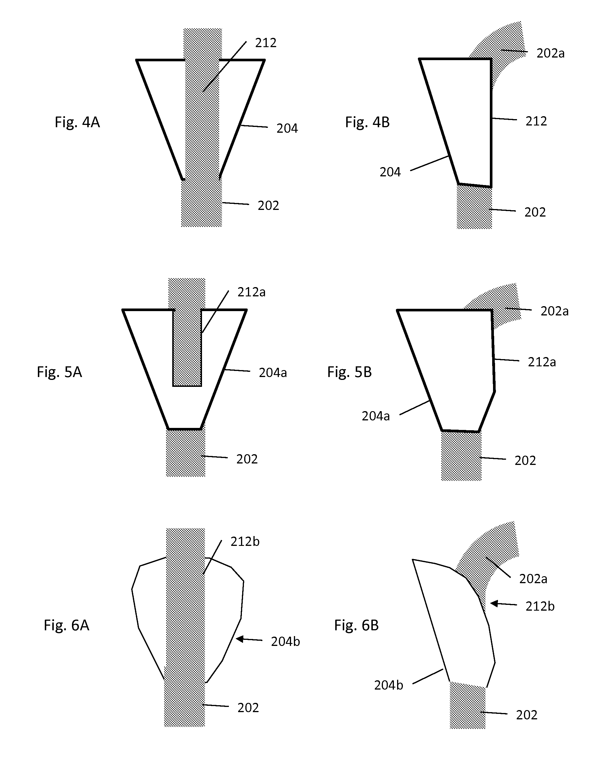
A flow directional infusion device includes a filter valve located at the distal end of a catheter. The filter valve constrains delivery of an embolic agent through the catheter to the locus of the aneurysm. In order to provide such delivery, the valve includes a longitudinal opening, radial opening or is otherwise partially permeable in a direction of the aneurysm so that the embolic agent or a delivery element for such agent is limited toward the aneurysm. In addition, the filter valve permits and directs blood flow within the blood vessel about the aneurysm during the treatment without obstructing the vessel and without allowing retrograde flow of the embolic agent in the vessel upstream of the aneurysm.

Description

CROSS-REFERENCE TO RELATED APPLICATION[0001]This application claims the benefit of U.S. Ser. No. 61 / 540,109, filed Sep. 28, 2011, which is hereby incorporated by reference herein in its entirety.BACKGROUND OF THE INVENTION[0002]1. Field of the Invention[0003]The present invention relates to methods and systems for treating blood vessels. More particularly, the invention relates to methods and systems for treating vascular malformations, such as aneurysms. Even more particularly, the present invention relates to methods and systems for treating an aneurysm with a microcatheter and an embolic agent.[0004]2. State of the Art[0005]An aneurysm is a localized, blood-filled balloon-like bulge in the wall of a blood vessel. Aneurysms can commonly occur in arteries at the base of the brain, i.e., at the circle of Willis. Another common type of aneurysm is an aortic aneurysm in the main artery carrying blood from the left ventricle of the heart.[0006]The development of an aneurysm causes a tu...

Claims


Application Information

Patent Timeline
IPC IPC(8): A61M25/00
CPCA61M25/0043A61M25/0097A61B17/12186A61B2017/1205A61M2039/2406A61M2205/7554A61M2205/75A61F2/01A61B17/12113A61M2205/7545A61M2039/2433
Inventor CHOMAS, JAMES E.WELDON, NORMAN R.PINCHUK, LEONARD
Owner TRISALUS LIFE SCI INC
Learn More