Distal Tip Assembly for a Heart Valve Delivery Catheter

a technology of distal tip and delivery catheter, which is applied in the field of catheters, can solve the problems of leading edge, distal tip of retaining sleeve,

Active Publication Date: 2013-03-28
MEDTRONIC ARDIAN LUXEMBOURG SARL
View PDF8 Cites 72 Cited by
  • Summary
  • Abstract
  • Description
  • Claims
  • Application Information

AI Technical Summary

Problems solved by technology

The exposed edge of the retaining sleeve can contact the wall of the body lumen or cavity, which can cause damage to the wall, especially in diseased body lumens.
For example, during a trans-femoral delivery of a heart valve prosthesis, the delivery catheter must navigate around the aortic arch, which can cause the retaining sleeve to bend and can expose the retaining sleeve's distal, leading edge.
The exposed leading edge of the retaining sleeve may damage the aortic wall if the edge contacts the wall.

Method used


Image

  • Distal Tip Assembly for a Heart Valve Delivery Catheter
  • Distal Tip Assembly for a Heart Valve Delivery Catheter
  • Distal Tip Assembly for a Heart Valve Delivery Catheter

Examples


Embodiment Construction

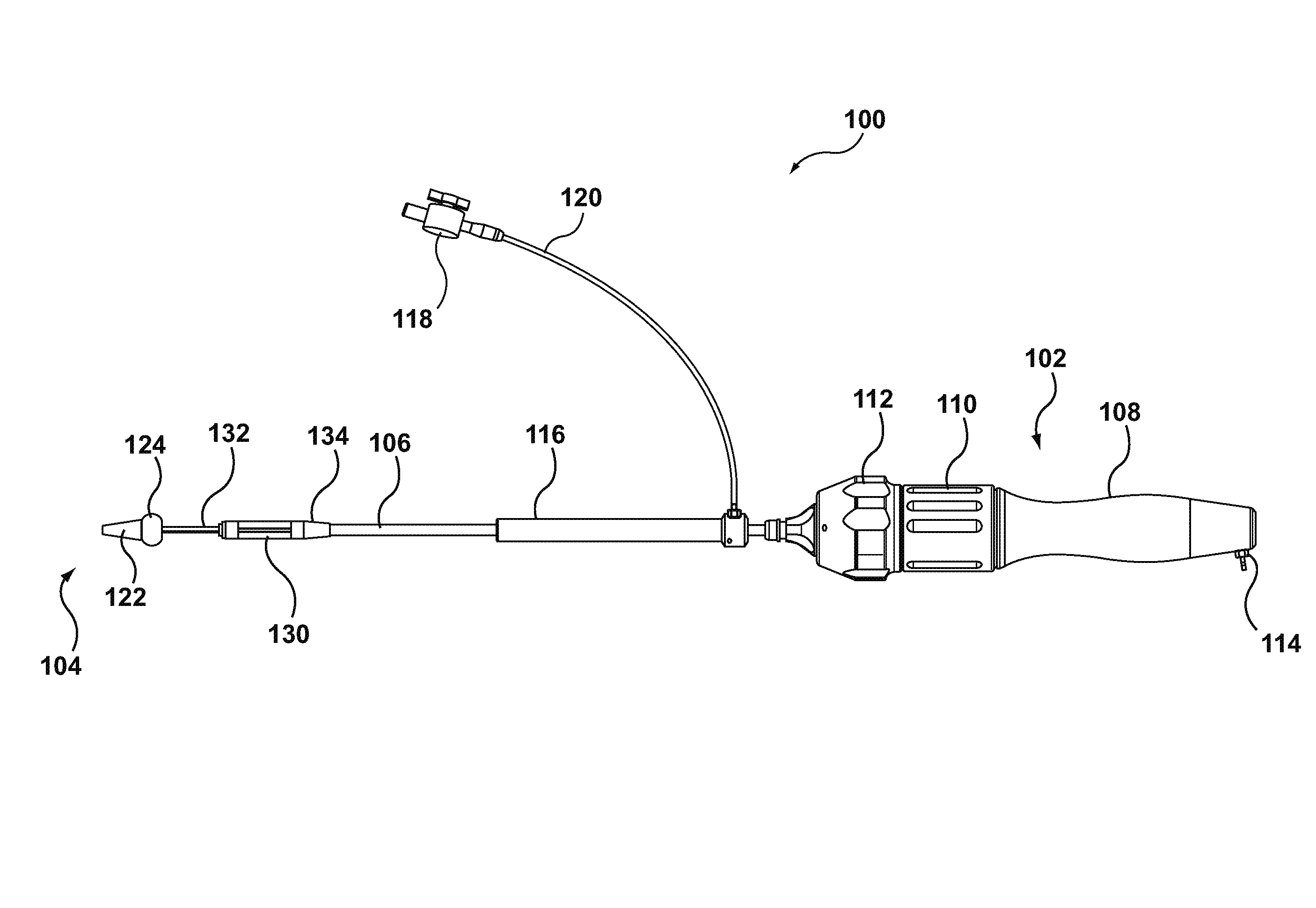
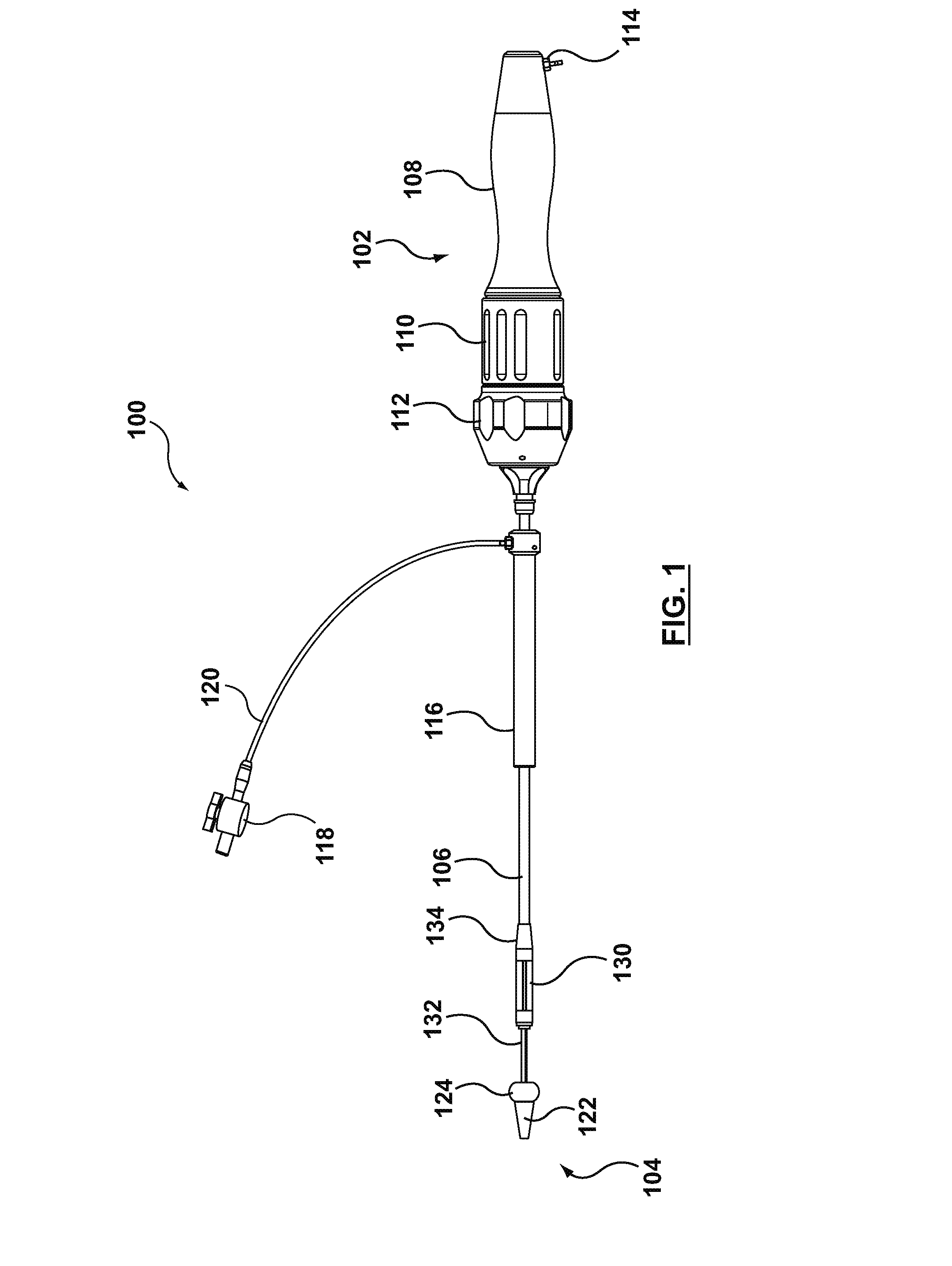
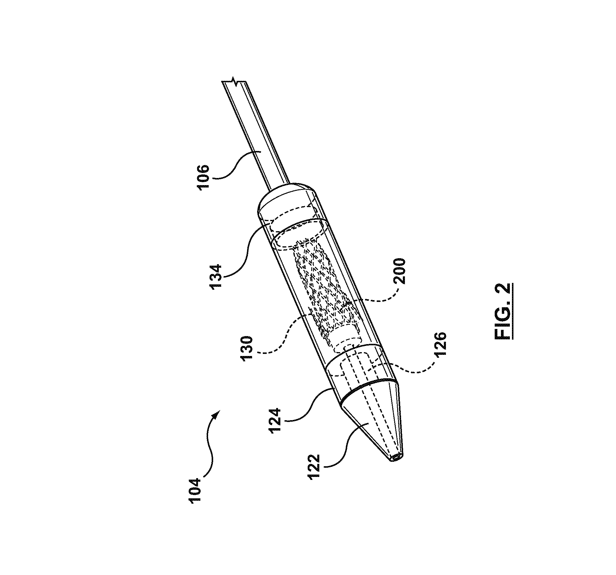
[0023]The following description of prosthesis delivery catheters and methods of delivering and implanting a prosthesis refers to the accompanying figures that illustrate exemplary embodiments. Other embodiments are possible. Modifications can be made to the embodiments described herein without departing from the spirit and scope of the present invention. Therefore, the following detailed description is not meant to be limiting. Further, it would be apparent to one of skill in the art that the systems and methods described below can be implemented in many different embodiments of hardware. Any actual hardware described is not meant to be limiting. The operation and behavior of the systems and methods presented are described with the understanding that modifications and variations of the embodiments are possible given the level of detail presented. For example, the delivery catheter described below can be adapted for use with different types of prostheses, for example, heart valve pro...


PUM


Abstract

A catheter assembly according to the present invention includes a handle assembly, an introducer sheath, and a distal tip assembly. The distal tip assembly can include first and second retaining sleeves and a slotted tip with a non-traumatic tip guard positioned at the proximal end of the slotted tip. The handle assembly can include a fixed main handle and two or more rotating handles that allow a user to control the distal tip assembly of the catheter. Each control knob on the handle assembly controls a portion of the components on the distal by of the catheter by allowing for precise manipulation of various delivery shafts. Each delivery shaft extends from the handle assembly to respective positions towards the distal end of the catheter.

Description

BACKGROUND[0001]1. Field[0002]The present invention relates to catheters for delivering a prosthesis and, particularly, to delivery catheters having an a traumatic distal tip assembly.[0003]2. Background[0004]Recently, minimally invasive approaches have been developed to facilitate catheter-based implantation of prostheses, for example, transcatheter aortic-valve prosthesis implantation. Typically, during transcatheter prosthesis implantations, a prosthesis is radially contracted onto a delivery catheter so that the prosthesis can be introduced into a body lumen, for example, into the femoral artery, the brachial artery, or the aorta, or into a body cavity, for example, a chamber of the heart (e.g., the ventricle). The contracted configuration of the prosthesis on the delivery catheter can be maintained by a retaining sleeve positioned over the prosthesis. Using the delivery catheter, the prosthesis can then be guided to the desired implantation site through the body lumen or body c...

Claims


Application Information

Patent Timeline
Patent Type & Authority Applications(United States)
IPC IPC(8): A61F2/24
CPCA61M25/0074A61M2025/0687A61F2/2436A61M25/0082
Inventor GALLAGHER, JOHN
Owner MEDTRONIC ARDIAN LUXEMBOURG SARL
Why Eureka
Try Eureka