Hair remover

a hair removal and hair technology, applied in the field of hair removalers, can solve the problems inability to easily introduce body hair between, etc., and achieve the effect of reducing the possibility of insufficient shaving of body hair

Active Publication Date: 2013-04-04
PANASONIC INTELLECTUAL PROPERTY MANAGEMENT CO LTD
View PDF48 Cites 4 Cited by
  • Summary
  • Abstract
  • Description
  • Claims
  • Application Information

AI Technical Summary

Benefits of technology

[0007]It is an object of the present invention to provide a hair remover, which can reduce the possibility that body hair is insufficiently shaved due to the interference in a body associated with a position limitation of a head unit with respect to a main unit.

Problems solved by technology

For this reason, when removing hair growing on an area having irregularities around, such as a biological surface of a base of arm or leg, the main unit or hand grasping the main unit interferes in the irregularities, and thereby the body hair is not easily introduced between the fixed and movable blades, and there is a possibility that hair growing on such an area is insufficiently shaved.

Method used


Image

  • Hair remover
  • Hair remover
  • Hair remover

Examples


embodiment 1

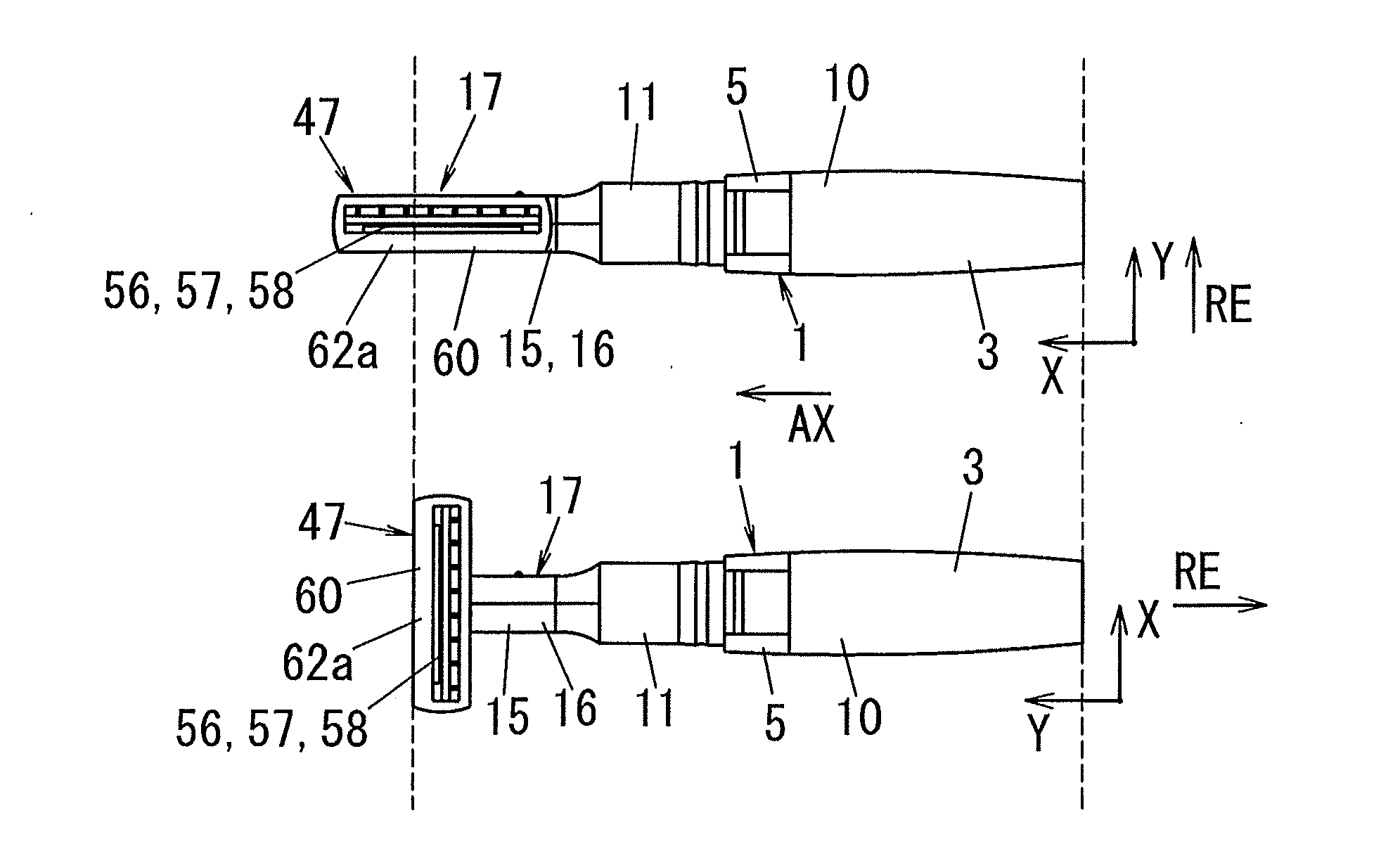
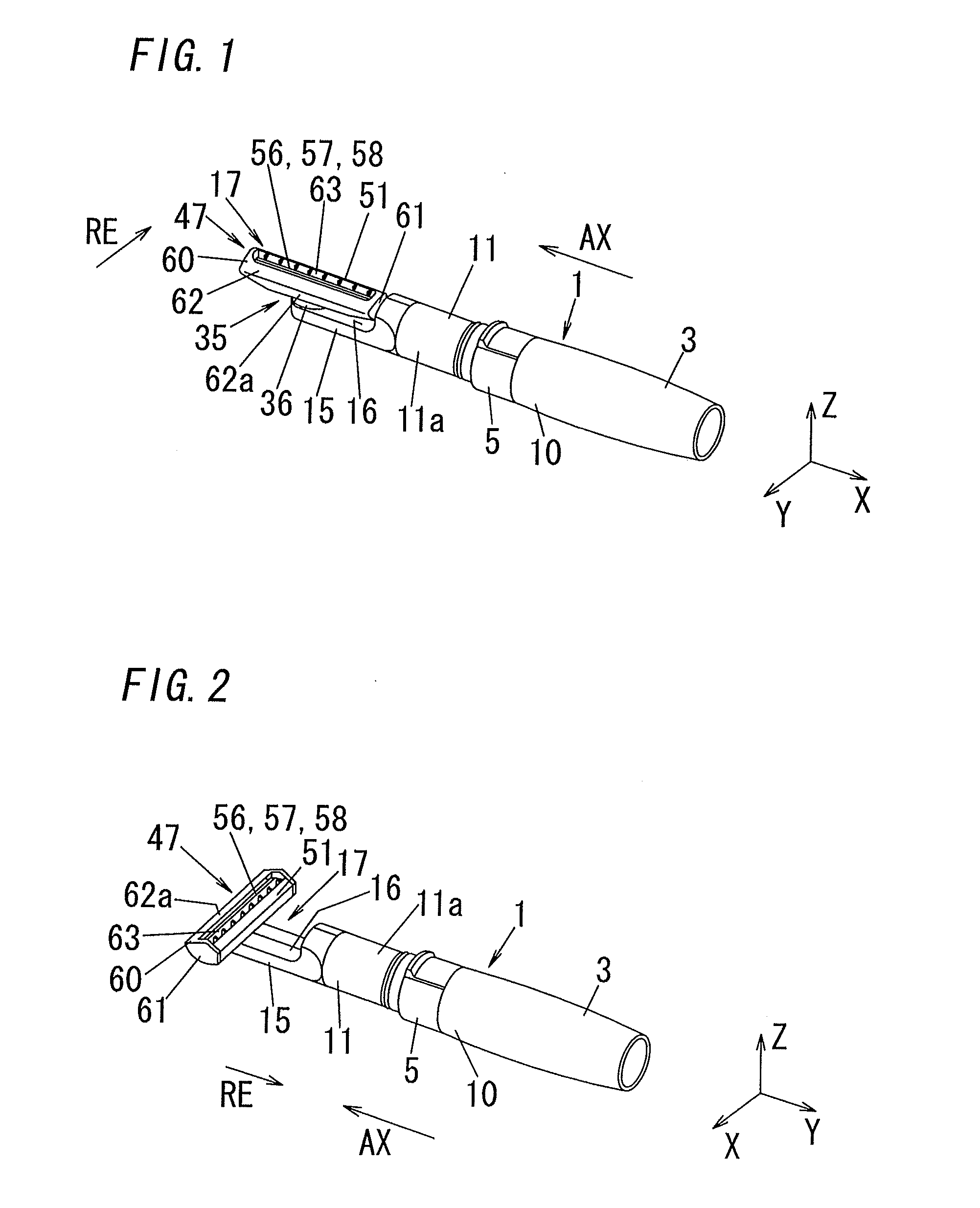
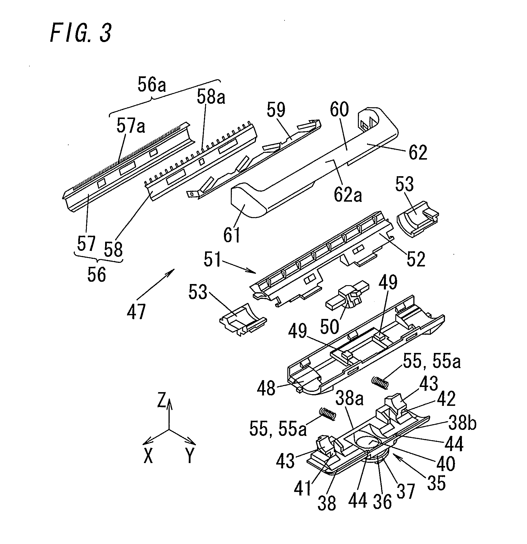
[0036]As shown in FIG. 1, a hair remover according to the present embodiment comprises: a main unit 1 having an electric source built in; a head unit 47 having a blade 56 for removing hair; a drive unit 20 (see FIG. 5) for driving head unit 47: and a cap 6 (see FIG. 16) detachably attached to main unit 1 so as to cover head unit 47.

[0037]As shown in FIG. 4, main unit 1 mainly comprises a battery (not shown) of the electric source, a battery cover 3 for replacing a battery, a housing 5 in which drive unit 20 is stored, and a seal holder 4 for detachably holding battery cover 3 in housing 5. Then, a casing of main unit 1 is formed into a hollow cylinder shape through housing 5 and battery cover 3. The cylinder part comprises a gripper 10 of which an outer periphery can be grasped by a user when using the hair remover, and a small diameter section 11 which has a smaller diameter than gripper 10. As shown in FIGS. 1 and 2, gripper 10 and small diameter section 11 are continuously formed...

embodiment 2

[0094]A hair remover of the present embodiment also comprises a rotating mechanical section 35 and a swinging mechanical section. However, the hair remover of the present embodiment is different from that of Embodiment 1 in the configuration of drive unit 20.

[0095]More specifically, as shown in FIG. 17, rotation shaft 22 of motor 21 is located so as to project within extension portion 15, and then pinion gear 24 engages with gear 31a of face gear 31 directly so as to be almost perpendicular to the rotation center.

[0096]As described above, in the hair remover of the present embodiment, transmission of the driving force through engagement of gear members is performed only in one location within drive unit 20. Therefore, drive unit 20 can have a simple configuration, and such a configuration can reduce loss of the driving force caused by engagement of gears or the like within drive transmission unit 23.

[0097]In addition, although the present invention has been described with reference ...


PUM


Abstract

Hair remover comprises main unit having gripper, head unit having blade for removing hair, and drive unit for driving blade. Direction of extension portion extended from one end is defined as extension direction. Direction in head unit along hair removing direction of blade is defined as first direction. Direction in head unit perpendicular to first direction is defined as second direction. Hair remover comprises rotating mechanical section having rotation center of which axis is perpendicular to extension direction, enabling head unit to rotate around rotation center with respect to main unit, and thereby switching between a state where second direction of head unit is parallel to extension direction and a state where second direction of head unit is perpendicular to extension direction. Drive unit comprises driving source and drive transmission unit transferring a driving force of driving source to head unit in said states.

Description

BACKGROUND OF THE INVENTION[0001]1. Field of the Invention[0002]The invention relates generally to hair removers and, more particularly, to a hair remover which cuts body hair by means of driving a blade.[0003]2. Description of the Related Art[0004]There has been a hair remover comprising a comb-shaped fixed blade and a comb-shaped movable blade. This kind of hair remover mainly comprises a head unit having the fixed blade and the movable blade, and a main unit provided in one end of its gripper with an extension portion. The head unit is located in the tip of the extension portion. Then, the head unit in the hair remover contacts with a biological surface on which body hair is sprouted, and the body hair is introduced between the fixed and movable blades. Then, the introduced body hair is sheared (cut off) with the fixed and movable blades, and thereby the body hair on the biological surface is removed. As such a hair remover, for instance, Japanese Patent Application Laid-Open No....

Claims


Application Information

Patent Timeline
Patent Type & Authority Applications(United States)
IPC IPC(8): B26B21/40
CPCB26B19/063B26B19/048B26B19/02
Inventor SHIMIZU, HIROAKIHASHIGUCHI, TETSURO
Owner PANASONIC INTELLECTUAL PROPERTY MANAGEMENT CO LTD
Why Eureka
Try Eureka