Cradle drive mechanism, a table, and a patient imaging and carrying apparatus

a drive mechanism and cradle technology, applied in the field of medical imaging equipment, can solve the problems of low movement accuracy of the cradle, high cost and complicated structure of the apparatus, and inconvenient operation for the physician to operate on the patien

Active Publication Date: 2013-04-04
GE MEDICAL SYST GLOBAL TECH CO LLC
View PDF27 Cites 9 Cited by
  • Summary
  • Abstract
  • Description
  • Claims
  • Application Information

AI Technical Summary

Problems solved by technology

It is also not convenient for the physician to operate on the patient while performing imaging for diagnosis due to the rear pedestal 23.
However, be...

Method used


Image

  • Cradle drive mechanism, a table, and a patient imaging and carrying apparatus
  • Cradle drive mechanism, a table, and a patient imaging and carrying apparatus
  • Cradle drive mechanism, a table, and a patient imaging and carrying apparatus

Examples


Embodiment Construction

[0018]Details of one or more embodiments of the present application will be explained in the description of the attached drawings and embodiments. Other features, objects and advantages of the present application can become apparent from the description, attached drawings and claims.

[0019]In order to solve the technical problem of lower movement accuracy in the cradles of prior art, embodiments of the present application provide a cradle drive mechanism.

[0020]The present application will be described in more detail in conjunction with embodiments. Those skilled in the art should understand that these embodiments are just some specific embodiments by way of examples, and are not intended to limit the present application and its scope.

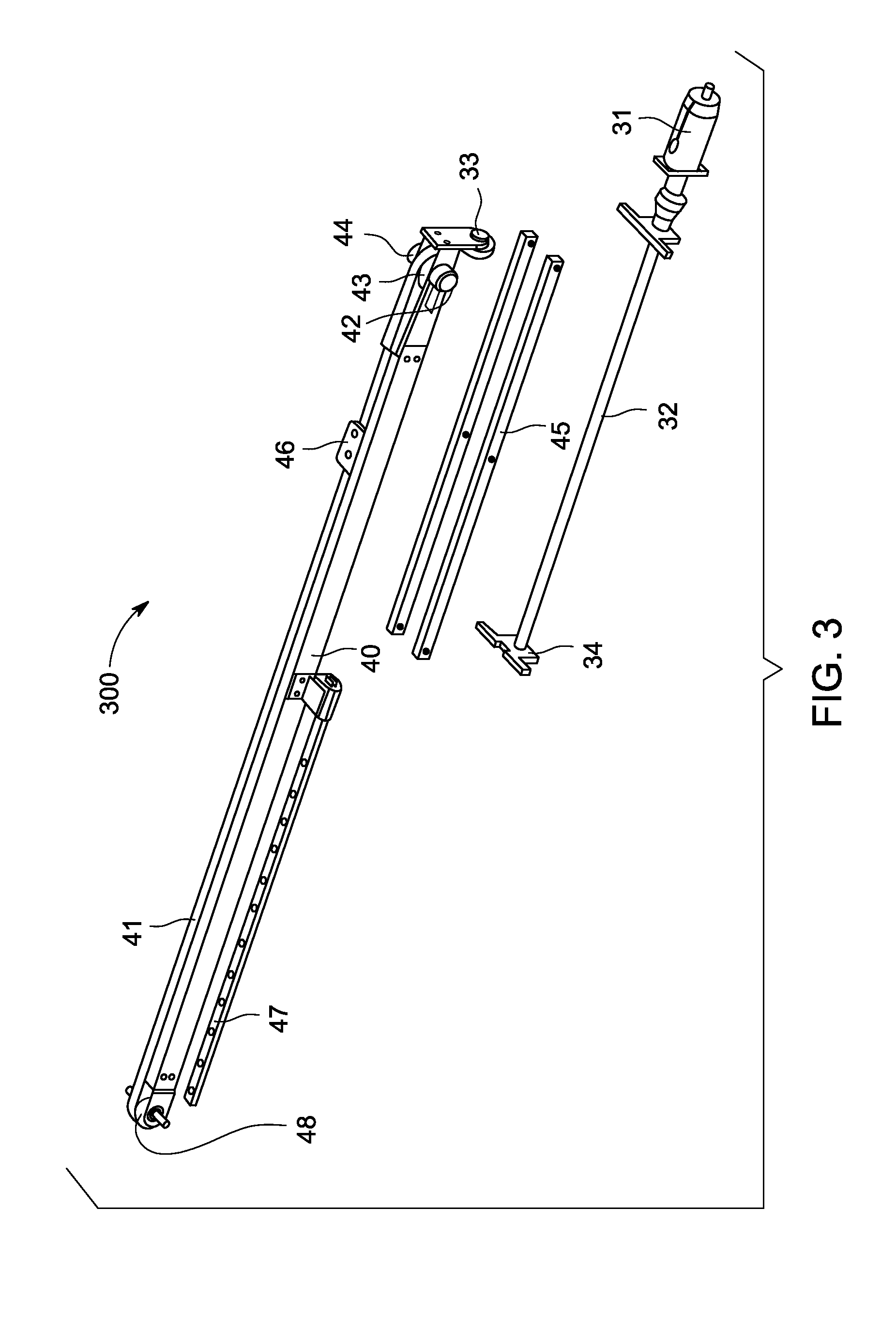
[0021]Referring to FIG. 3, a cradle drive mechanism 300 according to an embodiment of the present application is shown. The cradle drive mechanism 300 includes a drive motor 31; a screw and nut transmission device consisting of a screw 32 and a nut 33; a...


PUM


Abstract

A cradle drive mechanism is provided. The cradle drive mechanism includes a drive motor, an intermediate frame and a screw and nut transmission device driven by the drive motor so as to drive linear reciprocating motion of the intermediate frame. The cradle drive mechanism also includes a rotating, shaft having a first driving wheel and a gear, a transmission belt, and a rack meshed with the gear so that, during linear reciprocating motion of the intermediate frame, the rack forces the gear to rotate and drive rotation of the first driving wheel, wherein rotation of the first driving wheel drives rotation of the transmission belt. The cradle drive mechanism also includes a cradle connector fixed on the transmission belt and configured to connect a cradle and to drive linear reciprocating motion of the cradle.

Description

BACKGROUND OF THE INVENTION[0001]The present application relates to the field of medical imaging apparatus, and more particularly, to a cradle drive mechanism, a table having such cradle drive mechanism and a patient imaging and carrying apparatus having such table.[0002]Generally, a patient can be scanned and imaged by a variety of imaging techniques in order to make diagnosis Such imaging techniques can include magnetic resonance imaging (MRI), computer tomography (CT), X-ray imaging, positron emission tomography (PET) and the like. A patient imaging and carrying apparatus employing such imaging techniques generally includes a movable table so as to carry and position the patient accurately.[0003]As shown in FIG. 1, a patient imaging and carrying apparatus employing the magnetic resonance imaging technique usually includes the following three portions: a table 21, an imaging system 22 and a rear pedestal 23. In this apparatus, the imaging system 22 is a magnetic resonance imaging ...

Claims


Application Information

Patent Timeline
IPC IPC(8): F16H37/12
CPCF16H37/124F16H19/0604A61B6/0471A61B5/0555Y10T74/18104Y10T74/18088Y10T74/18664Y10T74/18752Y10T74/18576Y10T74/18152Y10T74/1812Y10T74/18808Y10T74/18056A61B5/055A61B5/704
Inventor FANG, XIANFAZHANG, GAOXIANHU, GANGYANG, XIN
Owner GE MEDICAL SYST GLOBAL TECH CO LLC
Why Eureka
Try Eureka