

Baseball bat support device
a technology for supporting devices and baseball bats, which is applied in the direction of light supporting devices, washstands, scaffold accessories, etc., can solve problems such as injuries to players, and achieve the effect of quick and convenient removal of securements
- Summary
- Abstract
- Description
- Claims
- Application Information
AI Technical Summary
Benefits of technology
Problems solved by technology
Method used
Image

Examples
third embodiment
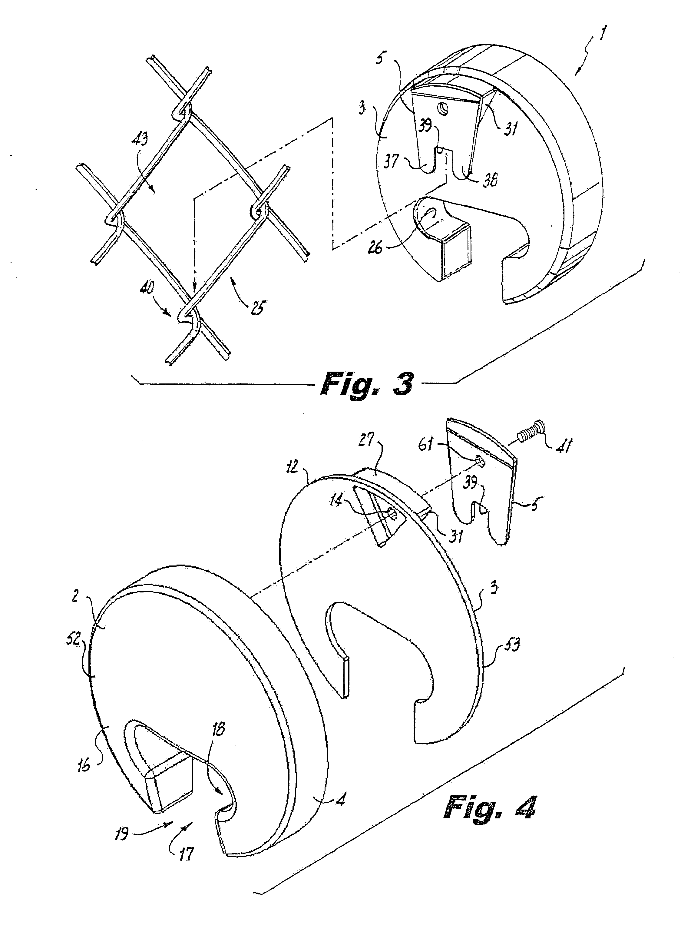
[0057]Also, in this third embodiment, and as shown in FIGS. 11-13, the attachment clip 5 is in the form of a flat planar disk 80 (which may also be rectangular or polygonal) which is affixed to the rear surface 74 of the spacer near the apex 33 thereof by a screw 76, adhesive or other means and which overhangs the apex 33 a predetermined distance so that the upper portion 78 of the link twist 40 is held captive between the disk-shaped attachment clip 27 and the back surface 12 of the main body 1 to prevent the bat holder from becoming dislodged from the chain-link fence 100.
fourth embodiment
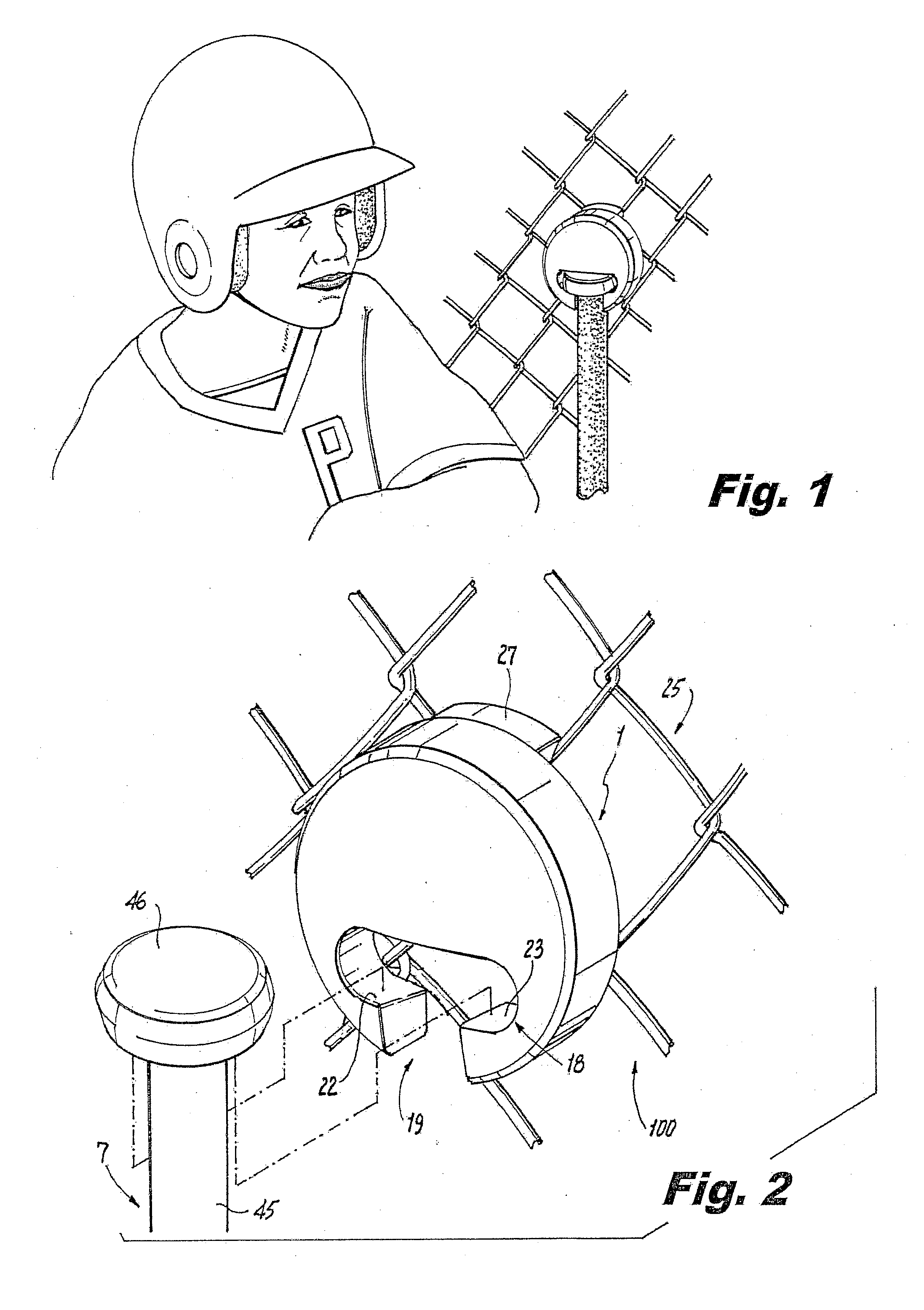
[0058]In yet the present invention, the bat holder may include a main body 1, such as described before, as well as a wedge-like spacer 27, such as can be seen from FIGS. 14-16 of the drawings. The spacer 27 also functions as the attachment clip 5, as will be described below.
[0059]More specifically, the spacer 27 is relatively thick, that is, about one inch or more in thickness, and has angled contact surfaces 31 which diverge from an apex 33 at an angle of preferably about 90 degrees. However, in this fourth embodiment, the spacer 27 includes recesses 35 formed by portions of the contact surfaces 31 being beveled toward the back surface 12 of the main body 1. These recesses 35 formed on the angled contact surfaces 31 of the spacer 27 receive therein one or both of the angled wires 84, 88 which are twisted together at a link 25 in the chain-link fence. More specifically, each wire 84, 88 defining a twist 40 in a chain-link fence 100 may be received by a corresponding recess 35 formed...
sixth embodiment
[0063]the baseball bat support device is shown in FIGS. 20-25. In this preferred form of the baseball bat support device, a lower portion 110 of the main body 1 is made thicker than the upper portion 112 of the main body so that the overall weight of the baseball bat support device is concentrated more in the lower portion 110 than in the upper portion 112 of the main body 1. This weight distribution concentrated in the lower portion 110 of the main body 1 will assist in stabilizing the baseball bat support device as it rests on the chain-link fence 100. The greater thickness of the main body 1 in the lower portion 110 of the baseball bat support device can be seen in the cross-sectional view of FIG. 22. Also, it is evident from FIG. 22 that, in the preferred form, the main body 1 is formed as a solid piece of material, such as plastic, wood or the like, to provide the baseball bat support device with greater weight and strength.
[0064]Also, as can be seen from FIGS. 21-23, the lower...
PUM
 Abstract
Description
Claims
Application Information