Modular Voltage Source Converter

a voltage source converter and module technology, applied in the direction of active power filtering, emergency protective circuit arrangement, transportation and packaging, etc., can solve the problems of large reactive power, high cost and time consumption, and large amount of reactive power carried

Active Publication Date: 2012-03-15
HITACHI ENERGY SWITZERLAND AG
View PDF5 Cites 46 Cited by
  • Summary
  • Abstract
  • Description
  • Claims
  • Application Information

AI Technical Summary

Benefits of technology

[0032]A major advantage of the present invention is that non faulty cell components of a cell module are continued to be used without adding on extra circuitry that require active control.
[0033]According to the present invention embodiments are disclosed for utilizing a faulty cell module despite a single failure to provide zero voltage at the terminals of the faulty cell module.
[0034]According to the invention it is assumed that when a fault occurs in the cell it only affects one phase leg of a cell module. Therefore it is possible to operate the non-faulty phase leg in such a way that it can provide zero ou...

Problems solved by technology

Such measures, however, are expensive and time-consuming, if they are at all feasible.
Out of the EAF may well come an abundance of distortion such as voltage fluctuations, harmonics and phase asymmetry.
Also, the grid may be subject to carrying large amounts of reactive power, which is unintended and gives rise to transmission and distribution losses as well as impedes the flow of useful, active power in the grid.
Also, the physical process inside the furnace (electric melting) is erratic in its nature, with one or several electrodes striking electric arcs between furnace and scrap.
As a consequence,...

Method used


Image

  • Modular Voltage Source Converter
  • Modular Voltage Source Converter
  • Modular Voltage Source Converter

Examples


Embodiment Construction

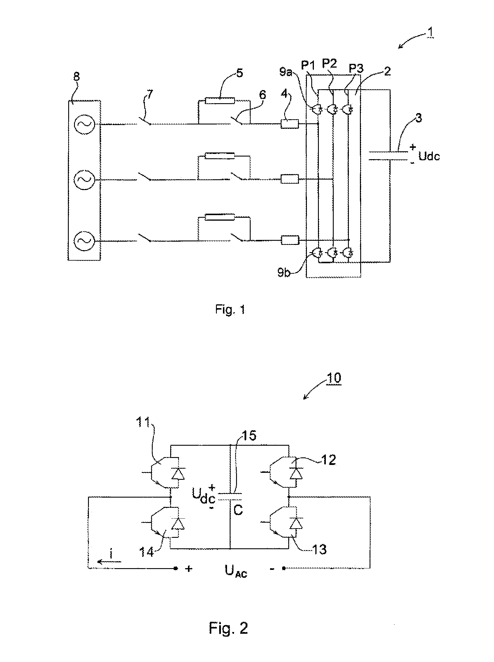
[0050]FIG. 1 illustrates a prior art two-level static compensator 1 without any transformers to step down the power network voltage. The static compensator 1 comprises a VSC 2 connected at its DC side to a capacitor 3 and at its AC-side to a power network 8, also denoted grid.

[0051]The conventional two-level VSC 2 comprises three phases P1, P2, P3 (the phases are denoted L1, L2, L3 when describing the present invention), each phase consisting of two series-connected valves. The two valves of phase P1 are indicated at reference numerals 9a, 9b. Each valve 9a, 9b in turn comprises a transistor with an anti-parallel diode, or rather, in order to manage high voltages, each valve comprises a number of series-connected transistors, for example IGBTs, each IGBT having an anti-parallel diode.

[0052]The VSC 2 is connected to the grid 8, in FIG. 1 comprising a three phase network, via a phase reactor 4, via an optional starting resistor 5 connected in parallel with a switch 6 and via an AC cir...


PUM


Abstract

Voltage source converter based on a chain-link cell topology including one or more phases, each of the phases having one or more series-connected chain-link cell modules connected to each other. The output voltage of the voltage source converter is controlled by control signals applied to the series-connected chain-link cell modules. In case of failure of a chain-link cell module, that module is controlled, by the control signals, such that zero output voltage is provided at its output voltage AC terminal.

Description

CROSS-REFERENCE TO RELATED APPLICATIONS[0001]The present application is a continuation of pending International Patent Application PCT / EP2009 / 052885 filed on Mar. 11, 2009 which designates the United States, and the content of which is incorporated herein by reference.FIELD OF THE INVENTION[0002]The invention generally relates to the field of power compensation in a high-voltage power network, and in particular to a modular voltage source converter and to a chain-link cell module for a voltage source converter according to the preambles of the independent claims. In addition the invention relates to a method in a voltage source converter.BACKGROUND OF THE INVENTION[0003]Modern society relies heavily upon electricity. With deregulation and privatisation, electricity has become a commodity as well as a means for competition. Power quality, as a consequence, is coming into focus to an extent hitherto unseen. Disturbances emanating from any particular load will travel far, and, unless p...

Claims


Application Information

Patent Timeline
IPC IPC(8): H02H7/122H02H7/12
CPCH02J3/18H02M1/32H02M7/793B60L15/007Y02E40/30H02M2001/325H02M2007/4835H02J3/1857H02M1/36Y02T10/64H02M1/325H02M7/4835Y02E40/10Y02E40/20
Inventor CHIMENTO, FILIPPODIJKHUIZEN, FRANSHASLER, JEAN-PHILIPPEHOSINI, FALAHJONSSON, TOMASLUNDBERG, PETERMONGE, MAURONORRGA, STAFFANSVENSSON, JAN R.TINGLOW, FREDRIK
Owner HITACHI ENERGY SWITZERLAND AG
Why Eureka
Try Eureka