System and method for conditioning air flow to a gas turbine

Inactive Publication Date: 2013-04-11
GENERAL ELECTRIC CO
View PDF2 Cites 91 Cited by
  • Summary
  • Abstract
  • Description
  • Claims
  • Application Information

AI Technical Summary

Benefits of technology

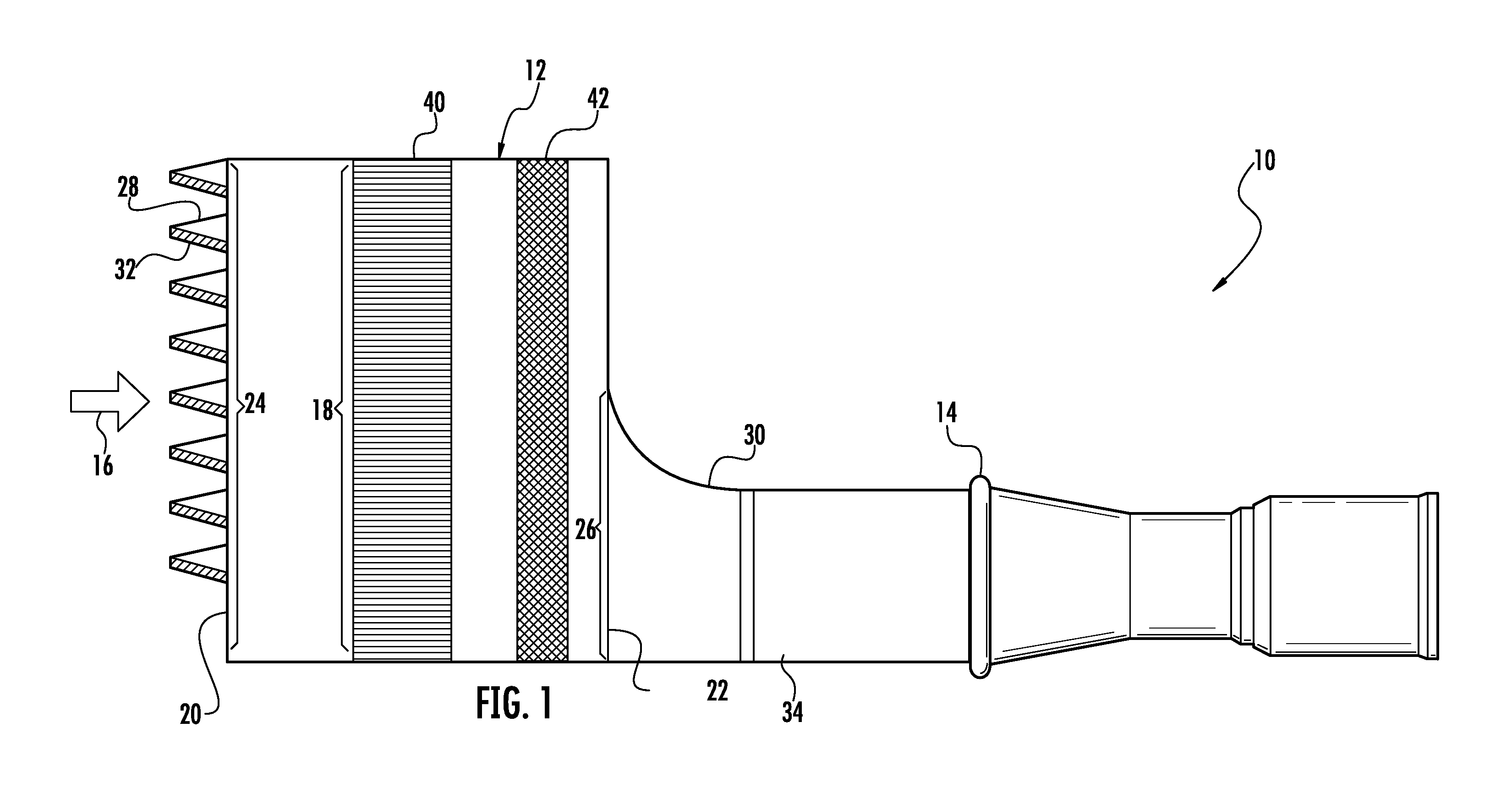
[0008]The present invention may also include a method for conditioning air flow to a gas turbine that includes flowing air through a filter housing connected to the gas turbine and flowing the air across a con

Problems solved by technology

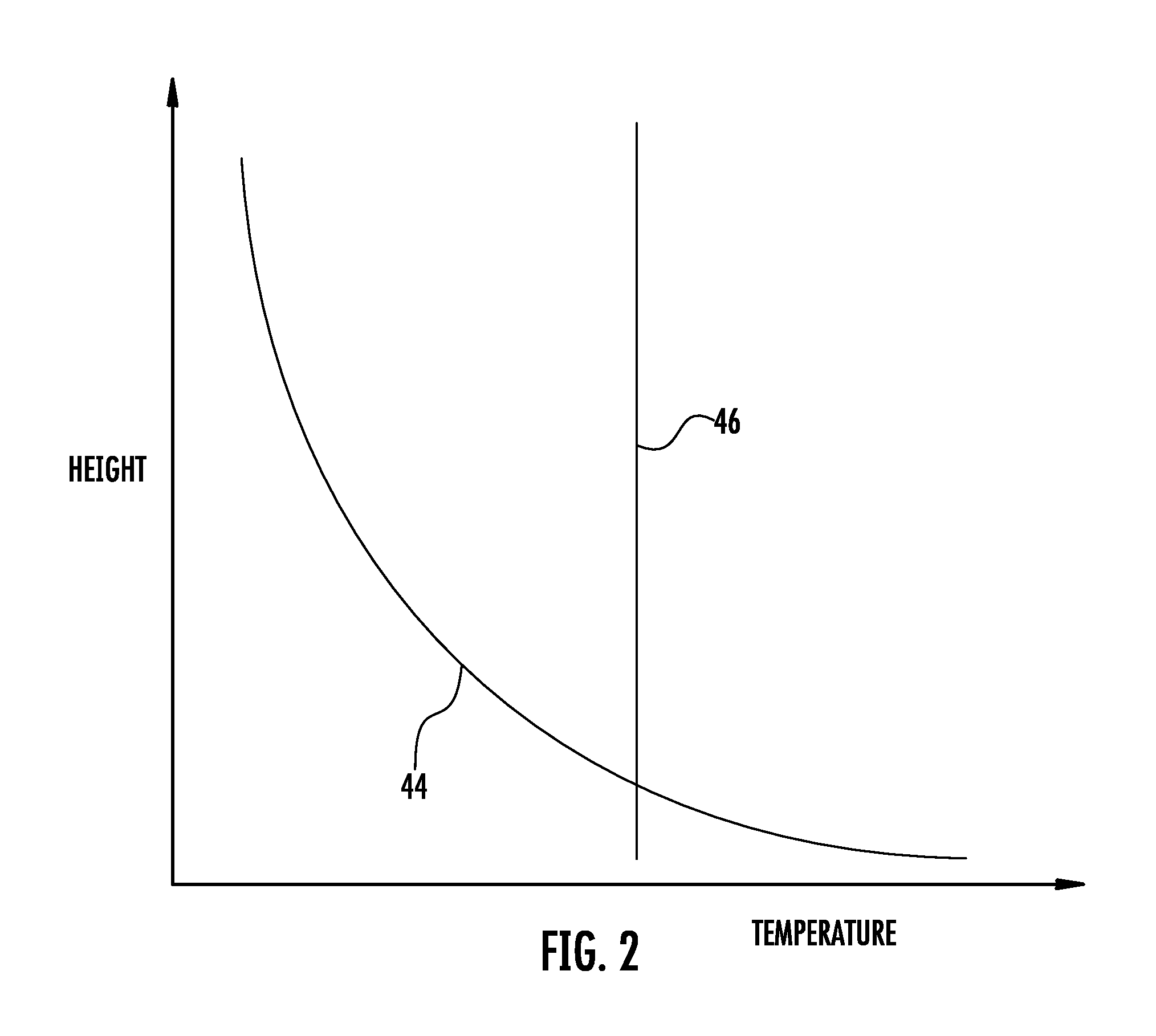
Although effective at adjusting the temperature and/or humidity of the ambient air, the physical limitations of the system may create an uneven temperature profile of the ambient air exiting the s

Method used


Image

  • System and method for conditioning air flow to a gas turbine
  • System and method for conditioning air flow to a gas turbine
  • System and method for conditioning air flow to a gas turbine

Examples


Example

[0019]Reference will now be made in detail to present embodiments of the invention, one or more examples of which are illustrated in the accompanying drawings. The detailed description uses numerical and letter designations to refer to features in the drawings. Like or similar designations in the drawings and description have been used to refer to like or similar parts of the invention.

[0020]Each example is provided by way of explanation of the invention, not limitation of the invention. In fact, it will be apparent to those skilled in the art that modifications and variations can be made in the present invention without departing from the scope or spirit thereof. For instance, features illustrated or described as part of one embodiment may be used on another embodiment to yield a still further embodiment. Thus, it is intended that the present invention covers such modifications and variations as come within the scope of the appended claims and their equivalents.

[0021]Various embodi...


PUM

PropertyMeasurementUnit
Temperatureaaaaaaaaaa
Densityaaaaaaaaaa
Depthaaaaaaaaaa

Abstract

A system for conditioning air flow to a gas turbine includes a filter housing and a conditioning media inside the filter housing to adjust the temperature of the air flowing through the filter housing. At least one of a depth or a density of the conditioning media varies across the filter housing. A method for conditioning air flow to a gas turbine includes flowing air through a filter housing connected to the gas turbine and flowing the air across a conditioning media in the filter housing. The method further includes conditioning the air flow to reduce the temperature difference of the air exiting the filter housing across a dimension of the filter housing.

Description

FIELD OF THE INVENTION[0001]The present invention generally involves a system and method for conditioning air flow to a gas turbine. In particular, various embodiments of the present invention vary at least one of a depth or density of a conditioning media to produce a desired temperature profile of the air flow to the gas turbine.BACKGROUND OF THE INVENTION[0002]Gas turbines are widely used in industrial and commercial operations. For example, industrial gas turbines typically include one or more combustors to generate power or thrust. A typical commercial gas turbine used to generate electrical power includes a compressor at the front, one or more combustors around the middle, and a turbine at the rear. Ambient air enters the compressor as a working fluid, and the compressor progressively imparts kinetic energy to the working fluid to produce a compressed working fluid at a highly energized state. The compressed working fluid exits the compressor and flows to the combustors where ...

Claims


Application Information

Patent Timeline
IPC IPC(8): B01D46/42
CPCF02C7/05F02C7/143F05D2300/522F05D2250/70F05D2250/71F28F13/14
Inventor SULLIVAN, MICHAEL ADELBERTVU, HUONG VANDESAI, BHALCHANDRA ARUNLAFONTAINE, ERIC M.COURNOYER, MARK ANDREW
Owner GENERAL ELECTRIC CO
Why Eureka
Try Eureka