Display device

a display device and display technology, applied in the field of display devices, to achieve the effect of flatness and flexibility

Active Publication Date: 2013-04-11
SHARP KK
View PDF5 Cites 22 Cited by
  • Summary
  • Abstract
  • Description
  • Claims
  • Application Information

AI Technical Summary

Benefits of technology

[0025]According to the present invention, the reinforcing member is bonded to the non-display region of the display panel such that the display region is exposed, so that the display device including the display panel having flexibility can exhibit both flatness and flexibility.

Problems solved by technology

Display devices such as liquid crystal display devices generally include display panels having glass substrates, and thus may be damaged by external impact.

Method used


Image

  • Display device
  • Display device
  • Display device

Examples


first embodiment

of the Invention

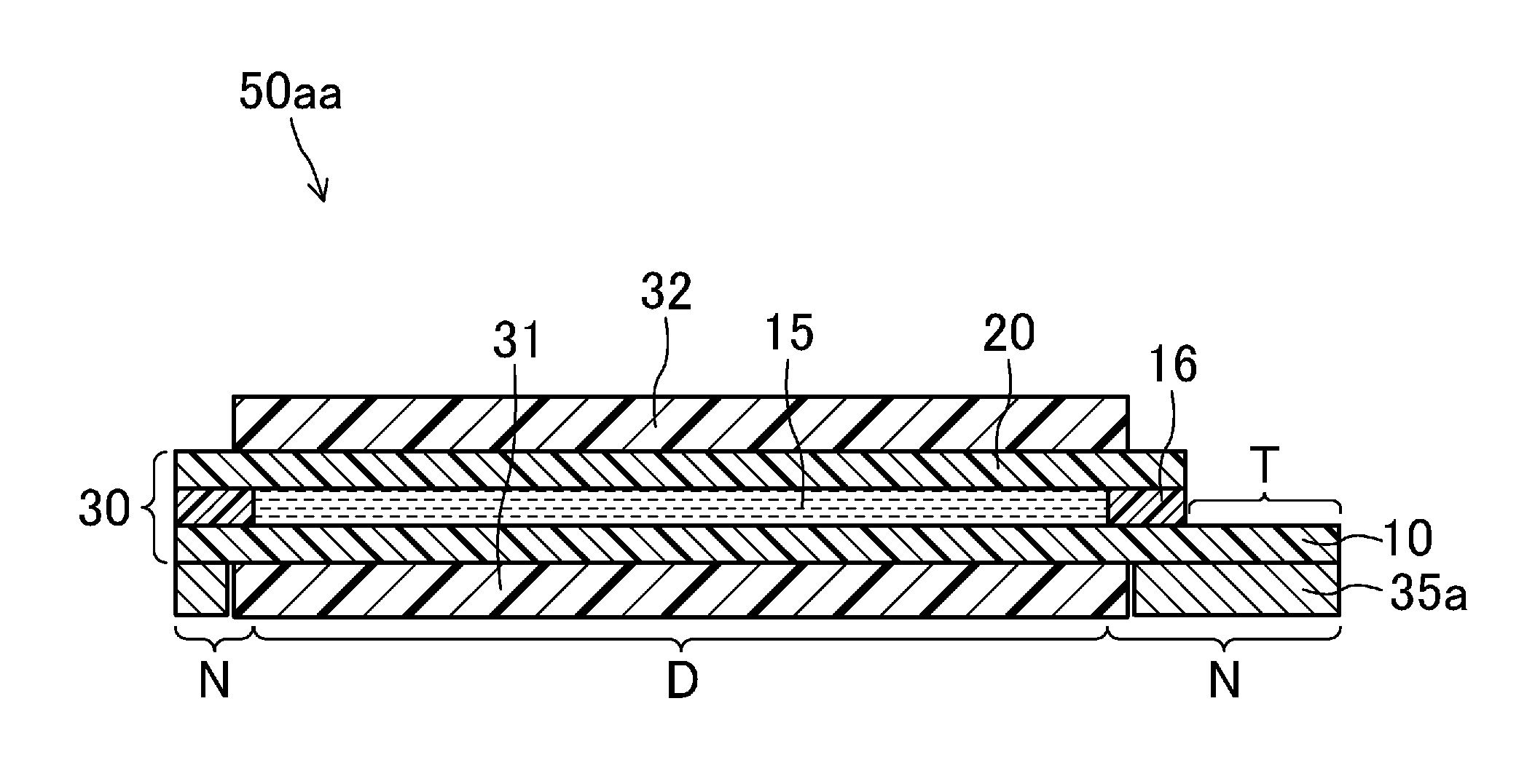
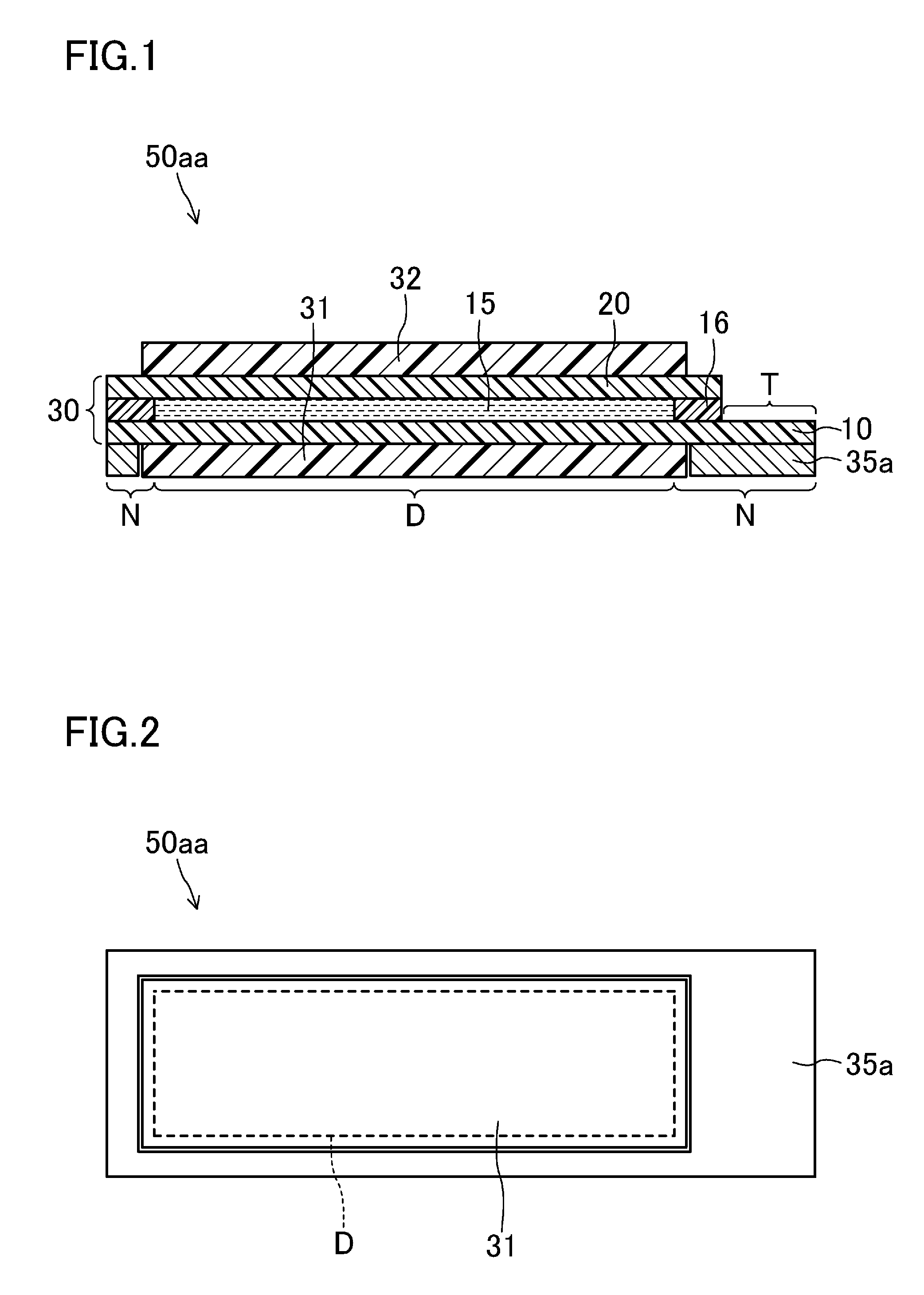
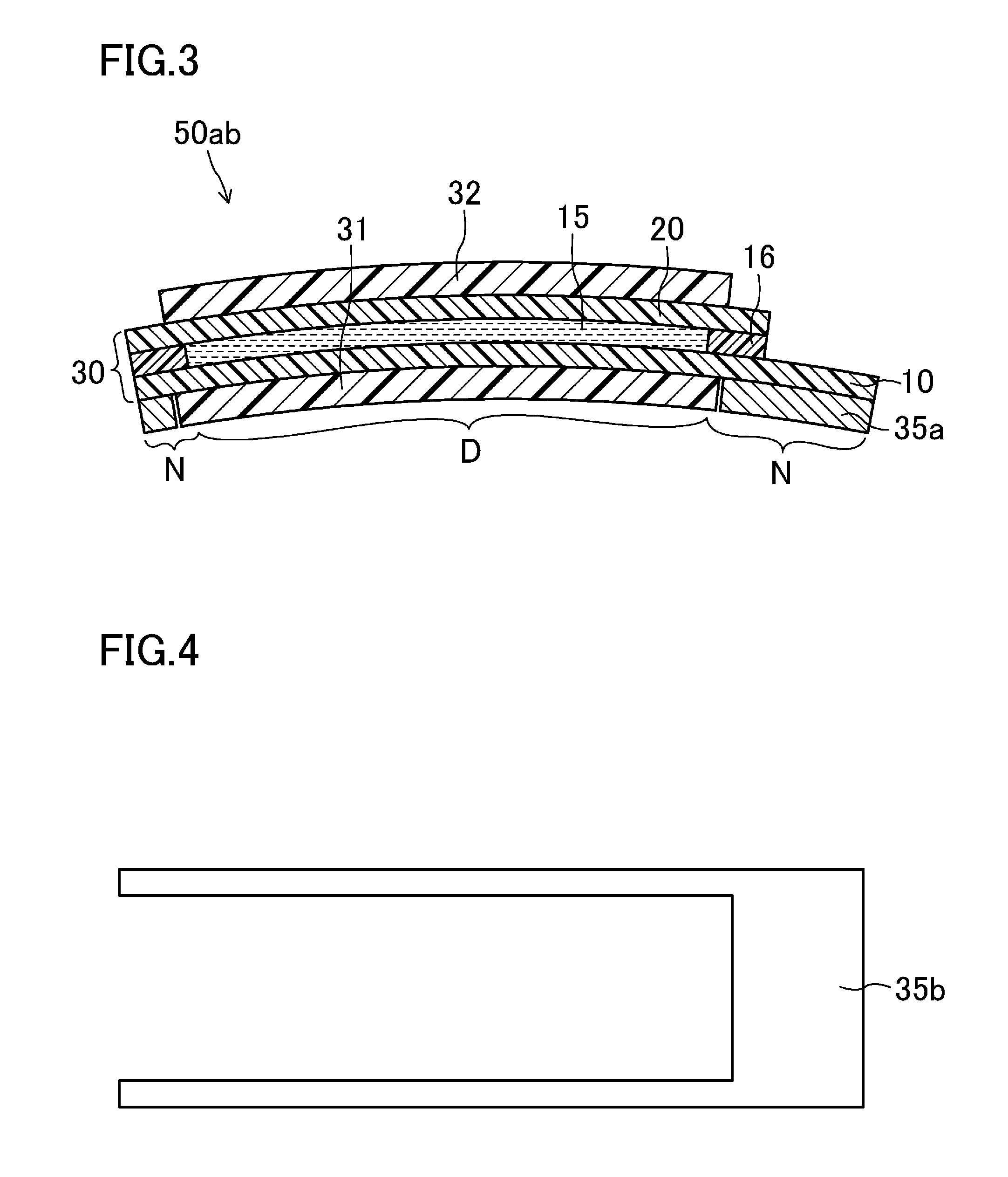
[0035]FIGS. 1-7 illustrate a first embodiment of a display device according to the present invention. Specifically, FIG. 1 is a cross-sectional view illustrating a liquid crystal display device 50aa of the present embodiment, and FIG. 2 is a plan view illustrating the liquid crystal display device 50aa, viewed from the back surface (from the bottom in FIG. 1). Moreover, FIG. 3 is a cross-sectional view of a liquid crystal display device 50ab of the present embodiment. Further, FIG. 4 is a plan view illustrating a reinforcing member 35b included in the liquid crystal display device of the present embodiment, and FIG. 5 is a plan view illustrating a reinforcing member 35c included in the liquid crystal display device of the present embodiment. Furthermore, FIG. 6 is a cross-sectional view illustrating a reinforcing member 35d included in the liquid crystal display device of the present embodiment, and FIG. 7 is a cross-sectional view illustrating a reinforcing member 3...

second embodiment

of the Invention

[0063]FIG. 8 is a cross-sectional view illustrating a liquid crystal display device 50b of the present embodiment. Note that in the following embodiment, the same reference numerals as those shown in FIGS. 1-7 are used to represent equivalent elements, and the explanation thereof will be omitted.

[0064]The first embodiment has illustrated the liquid crystal display devices 50aa and 50ab in which configurations of a backlight unit and a mounted member are omitted. The present embodiment specifically illustrates a liquid crystal display device 50b to which a backlight unit is provided, and a mounted member is pressure-bonded.

[0065]As illustrated in FIG. 8, The liquid crystal display device 50b includes a liquid crystal display panel 30, polarizing plates 31 and 32 respectively bonded to a back surface (a lower surface in the figure) and a front surface (an upper surface in the figure) of the liquid crystal display panel 30, a reinforcing member 35a bonded to the liquid ...


PUM

PropertyMeasurementUnit
heat temperatureaaaaaaaaaa
thicknessaaaaaaaaaa
thicknessaaaaaaaaaa

Abstract

A display device (50aa) includes a display panel (30) which has a display region (D) for image display and a non-display region (N) surrounding the display region (D), and has flexibility, wherein a reinforcing member (35a) is bonded to in the non-display region (N) of the display panel (30) such that the display region (D) is exposed.

Description

TECHNICAL FIELD[0001]The present invention relates to display devices, and specifically to a display device including a display panel which has a flexible substrate and flexibility.BACKGROUND ART[0002]Display devices such as liquid crystal display devices generally include display panels having glass substrates, and thus may be damaged by external impact.[0003]For example, Patent Document 1 discloses a display device including a display panel having a pair of glass substrates, a metal upper frame disposed above the display panel to store the display panel, and a buffer member made of a foamed material and disposed between the upper frame and an upper surface of one of the glass substrates included in the display panel. Patent Document 1 describes that this configuration can reduce damage on the display panel caused by impact, such as dropping impact.CITATION LISTPatent Document[0004]PATENT DOCUMENT 1: Japanese Patent Publication No. 2006-154366SUMMARY OF THE INVENTIONTechnical Probl...

Claims


Application Information

Patent Timeline
Patent Type & Authority Applications(United States)
IPC IPC(8): G02F1/1333
CPCG02F1/133305G02F1/133308G02F2001/133317G09F9/301G02F2201/54G02F1/1333G02F2001/133388G02F1/133317G02F1/133388
Inventor WATANABE, NORIKOYASUMATSU, TAKUTO
Owner SHARP KK
Why Eureka
Try Eureka