Surface shape determining device for a machining apparatus and surface shape determining method

a technology of surface shape and machining apparatus, which is applied in the direction of fluid pressure control, fluid tightness measurement, instruments, etc., can solve the problems of inability to measure the troublesome measuring operation, and poor surface shape of a measured object, so as to improve the accuracy of working work, the effect of flatness of the measured object and promotion of the accuracy of the shape of the measured obj

Inactive Publication Date: 2005-12-29
KOMATSU NTC LTD
View PDF22 Cites 7 Cited by
  • Summary
  • Abstract
  • Description
  • Claims
  • Application Information

AI Technical Summary

Benefits of technology

[0053] According to the invention described in aspect 2, in addition to an effect of the invention described in aspect 1, the position of the stepped portion or the hole formed at the measured object can be calculated by the surface shape calculating unit.
[0054] According to the invention described in aspect 3, in addition to an effect of the invention described in aspect 1, the flatness of the measured object can be calculated by the surface shape calculating unit.
[0055] According to the invention described in aspect 4, in addition to the effect of the invention described in aspect 1, the center coordinates of the plurality of holes formed at the work as the measured object, the hole diameter and the center interval distance of the hole can be calculated by the surface shape calculating unit, the means for calculating the center coordinates of the hole, the means for calculating the hole diameter and the means for calculating the center interval distance of the plurality of holes.
[0056] According to the invention described in aspect 5, in addition to an effect of the invention described in aspect 1, by the nozzle movement control unit, the nozzle can be moved at the constant speed by the main spindle device in the state of maintaining the distance between the front end of the nozzle of the fluid injecting unit and the surface of the measured object constant by the nozzle movement control unit and therefore, accuracy of determining the shape of the measured object can be promoted.
[0057] According to the invention described in aspect 6, in addition to the effect of the invention described in aspect 1, the amount of moving the main spindle device in the three axes directions of the working data of the work can be corrected. Therefore, accuracy of the working the work can be promoted.
[0058] According to the invention described in aspect 7, in addition to the effect of the invention described in aspect 1, the amount of changing the pressure per the unit distance of the initial coordinates and pressure data in the X axis and the Y axis directions can be set to be large, and accuracy of correcting the amount of moving the main spindle device in the three axes directions can be promoted by promoting accuracy of detecting the pressure.

Problems solved by technology

In measuring a displacement by using the sensors, reliability against resistance to environment, adverse environment as in in-line operation, coolant mist, chip or a change in temperature is poor, and there poses a problem of, for example, reading an error, a temperature drift or biting a chip or the like.
However, according to the position detecting apparatus of the JP-A-2002-357410, there poses a problem that although the position of the measured portion of the work or the like can be detected, a surface shape of a measured object cannot be measured.
Therefore, there poses a problem that measuring operation is troublesome, measuring time is prolonged.
Further, it is difficult to follow a change in the hole diameter and furthermore, it is difficult to apply to the work hole having a small hole diameter.

Method used


Image

  • Surface shape determining device for a machining apparatus and surface shape determining method
  • Surface shape determining device for a machining apparatus and surface shape determining method
  • Surface shape determining device for a machining apparatus and surface shape determining method

Examples


Embodiment Construction

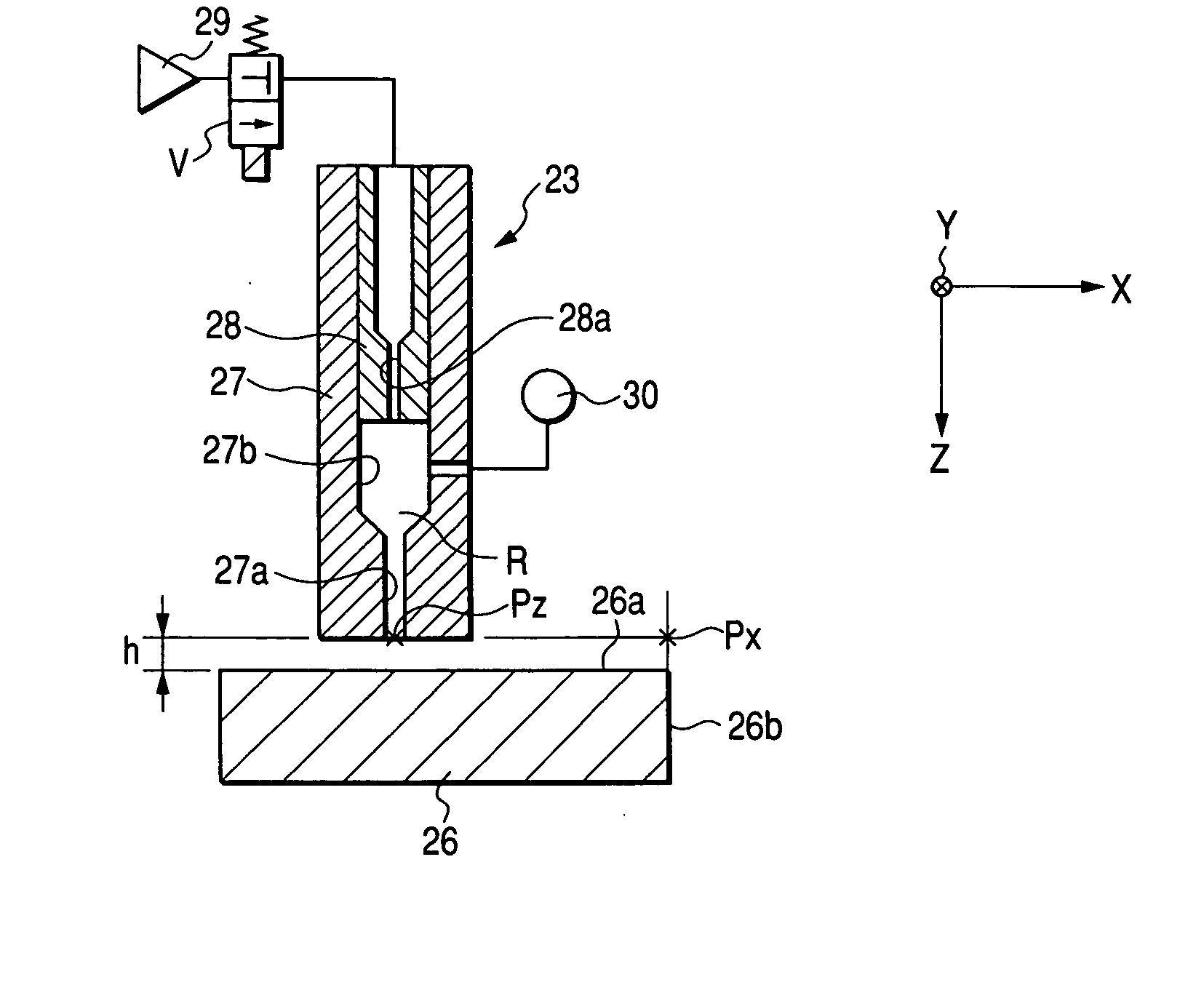
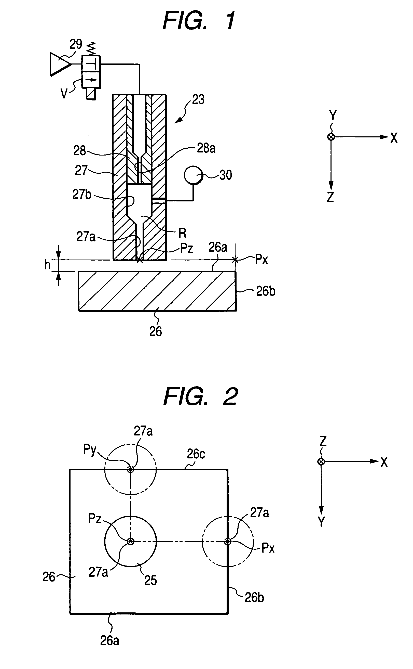
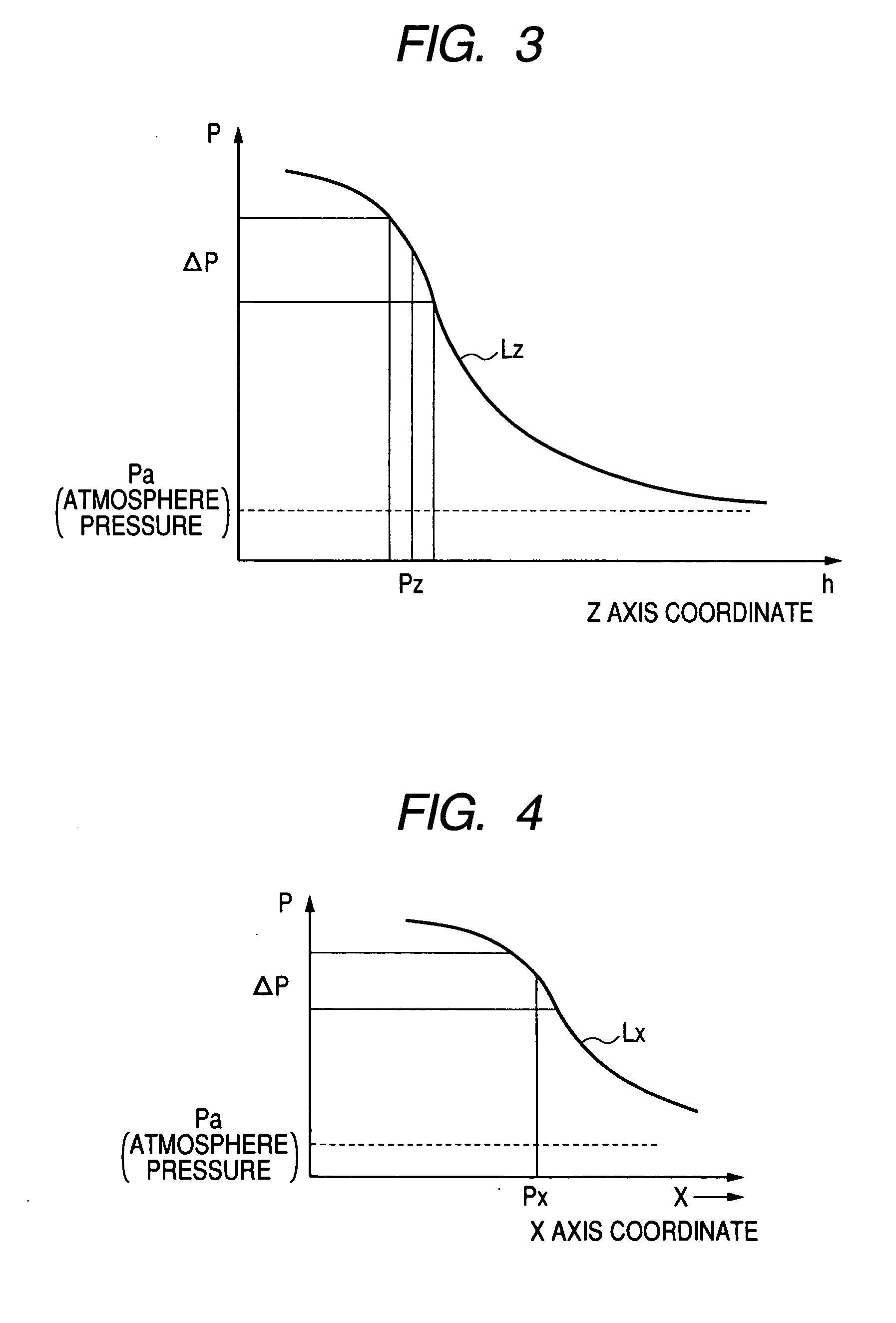
[0072] An explanation will be given of an embodiment of a surface shape determining device embodying the invention in reference to FIG. 1 through FIG. 10 as follows.

[0073] First, an outline constitution of a machine tool will be explained. As shown in FIG. 6, an upper face of a bed 11 is mounted with a work supporting table 12 for supporting a work W as a measured object. A Z axis guide rail 13 is laid on an upper face of the bed 11, and a Z axis saddle 14 is supported by the Z axis guide rail 13 reciprocatably in a Z axis direction (left and right direction of FIG. 6) by a Z axis drive mechanism 40A (refer to FIG. 7), mentioned later. An X axis guide rail 15 is laid on an upper face of the Z axis saddle 14, and an X axis saddle 16 is mounted to the X axis guide rail 15 reciprocatably in an X axis direction (direction orthogonal to paper face of FIG. 6) by an X axis drive mechanism 40B (refer to FIG. 7), mentioned later. A column 17 is erected at an upper face of the X axis saddle ...


PUM


Abstract

In a state of separating a front end face of an air injecting nozzle 23 from a worked work W by a predetermined interval h, the air injecting nozzle 23 is moved at a constant speed in an X axis direction, injects air from an injecting hole 27a of a nozzle main body 27 and is moved to pass centers O1, O2 of worked holes Wb, Wc of the work W. A variation in a pressure is measured by a pressure measuring unit 30. X axis coordinates of the centers O1, O2 of the holes Wb, Wc, a hole diameter E and a center interval distance D1 are calculated based on coordinates of center points T1, T2 of inclined portions Ld, Lu of a curve Lx of the pressure relative to the measured X axis coordinate.

Description

[0001] The present invention claims foreign priority to Japanese patent application no. P.2004-188537, filed on Jun. 25, 2005, the contents of which is incorporated herein by reference. BACKGROUND OF THE INVENTION [0002] 1. Field of the Invention [0003] The present invention relates to a surface shape determining device. [0004] 2. Description of the Related Art [0005] Generally, in a machine tool, a work is supported by an upper face of a bed via a work supporting table and the work is worked by a tool mounted to a main spindle device numerically controlled to move respectively in three axes directions of X, Y, Z axes similarly on the upper face of the bed. For measuring a position in a Z axis direction of the main spindle device, there are various methods of using, for example, measurement of length by laser, a proximity sensor or a touch sensor or the like. In measuring a displacement by using the sensors, reliability against resistance to environment, adverse environment as in in...

Claims


Application Information

Patent Timeline
Patent Type & Authority Applications(United States)
IPC IPC(8): B23Q17/00B23Q17/20G01B5/26G01B13/10G01B13/16G01B13/20G01B13/22G01B21/28G06F15/00G06F19/00
CPCG01B13/16G01B13/10B23Q15/00B23Q17/20
Inventor KAWASAKI, YUKIONISHIZAKI, TERUHIROMURAI, SHIROSASAKI, HISAO
Owner KOMATSU NTC LTD
Why Eureka
Try Eureka