Screen and screen unit

a screen and unit technology, applied in the field of screens and units, can solve the problems of abnormal display of images, scratches on the external appearance of reflection films, similar problems, etc., and achieve the effect of reducing the bends produced by the step of junction and improving the flatness of the screen bas

Active Publication Date: 2013-01-31
SEIKO EPSON CORP
View PDF1 Cites 9 Cited by
  • Summary
  • Abstract
  • Description
  • Claims
  • Application Information

AI Technical Summary

Benefits of technology

[0017]According to the screen having this structure, the supplementary base is connected to the second surface of the screen base, while the protection member is disposed in the vicinity of the surface of the one end of the supplementary base. Thus, the supplementary base is not damaged by its own edge at the one end when the supplementary base is wound. Generally, the junction area between the supplementary base and the screen base has a step in the thickness direction. When the junction area having such a step is left wound for a long period, linear bends are produced at the overlapping position between the screen base and the step. In this case, the flatness of the screen base decreases at the time of use, causing distortion of an image formed by the projection light. According to the structure of this application example which has the protection member in the vicinity of the face of the one end of the supplementary base, however, the junction area between the supplementary base and the screen base elastically deforms the protection member in the winding condition of the screen, while producing a clearance between the junction area and the protection member. In this case, the step becomes lower in the winding condition of the screen, and bends produced by the step decrease. Accordingly, the flatness of the screen base improves.Application Example 5
[0019]According to the screen having this structure, the protection member is provided on the area including the junction between the supplementary base and the second surface of the screen base. In this case, the supplementary base is not damaged by its own edge at the one end when the supplementary base is wound. Moreover, similarly to Application Example 4, bends produced by the step decrease, and the flatness of the screen base improves.Application Example 6

Problems solved by technology

In this case, the projections in contact with the rear surface scrape against the rear surface, whereby a part of the projections collapse in their shapes and leave scratches on the external appearance of the reflection film.
These scratches on the reflection film adversely affect normal reflection of the light projected from the projector, and cause abnormal display of the image.
In addition, in the case of the structure which includes an extension screen base joined to a screen containing a reflection film, similar problems occur due to the contact between the projections and the edge of the junction area.
However, in the area where the winding step preventing members are not provided, the front surface and the rear surface of the screen overlap with each other, wherefore similar problems arise.
In this case, the flatness of the screen base decreases at the time of use, causing distortion of an image formed by the projection light.

Method used


Image

  • Screen and screen unit
  • Screen and screen unit
  • Screen and screen unit

Examples


Embodiment Construction

[0029]An exemplary embodiment is hereinafter described with reference to the drawings.

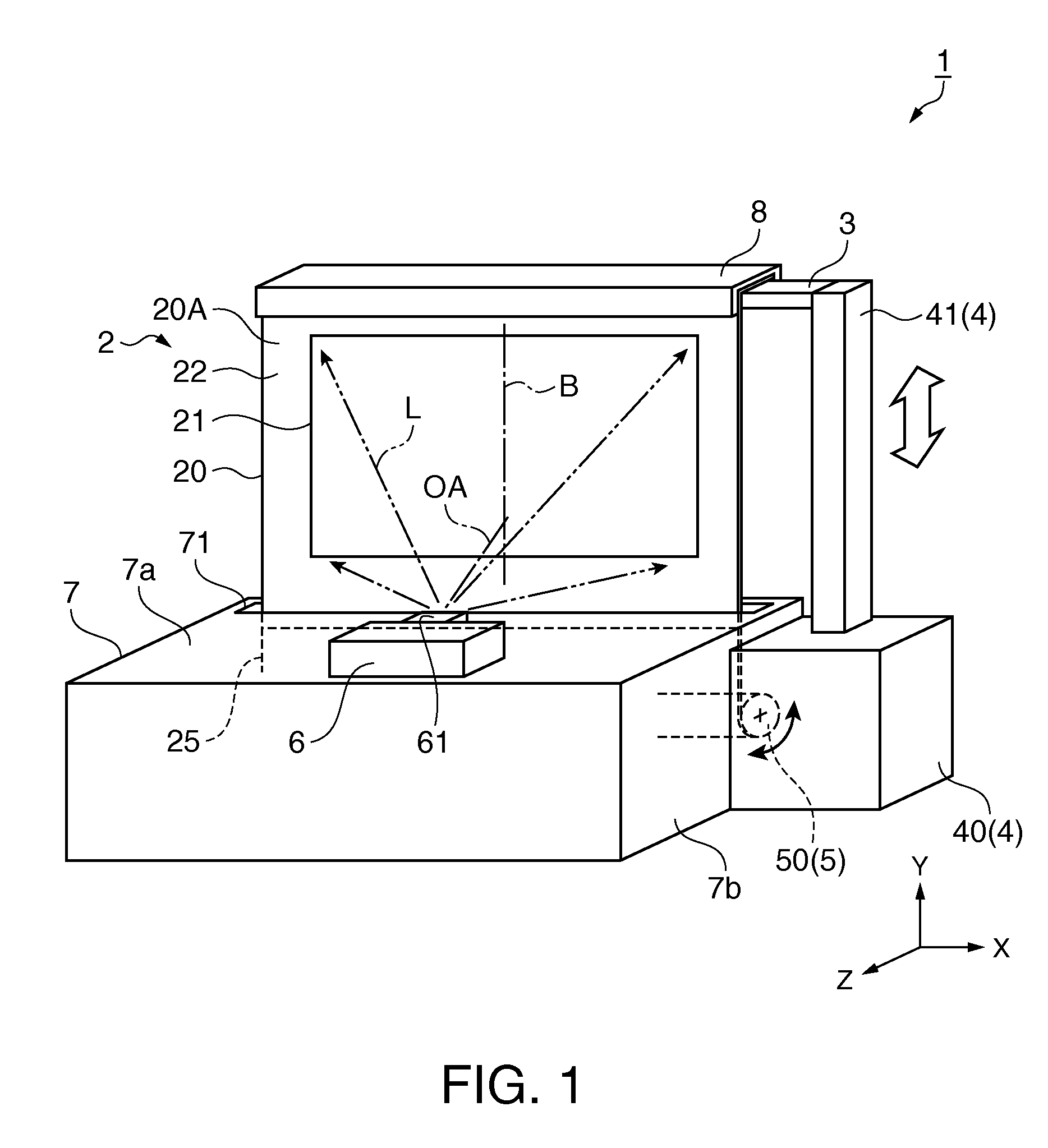
[0030]FIG. 1 schematically illustrates a screen unit 1 according to an embodiment. The general structure of the screen unit 1 in this embodiment is now briefly explained in conjunction with FIG. 1.

[0031]The screen unit 1 according to this embodiment is a reflection type screen unit placed on a floor surface or the like for use. The screen unit 1 comes into a condition for use when a substantially rectangular screen 2 of the screen unit 1 is drawn out in the upward direction (direction substantially perpendicular to the floor surface) from the inside of a rectangular parallelepiped and box-shaped housing 7 in accordance with the cooperative actions of an expanding and contracting mechanism 4 and a winding mechanism 5 so as to stand on the floor surface. In this condition, the screen 2 reflects projection light L received from a projector 6 attached to the housing 7 such that the projection light L c...


PUM


Abstract

A screen reflects projection light for display. The screen has a screen base designed to be wound and including a first surface (front surface) and a second surface (rear surface) on the side opposite to the front surface. The front surface contains a display area that has a reflection film on which the projection light is reflected. The screen further has a flexible protection member which is disposed on the portion of the rear surface corresponding to the outside of the display area in the width direction of the display area, and extends through substantially the full length of the display area in the winding direction of the display area. The front surface is positioned outside when the screen base is wound.

Description

BACKGROUND[0001]1. Technical Field[0002]The present invention relates to a screen and a screen unit.[0003]2. Related Art[0004]A screen unit known in the art has a screen which reflects light projected from a projection type display apparatus such as a projector for display of an image on the screen. There is disclosed in JP-A-2007-328111, a screen which has a first winding step preventing member and a second winding step preventing member disposed at one and the other ends of the rear surface of the screen, respectively, in the direction perpendicular to the direction where a screen main body and a non-screen body are joined and arranged side by side. Each of the first and second winding step preventing members is located at a position not overlapping with the junction area between a first end and a second end of the two bodies. According to this structure, the screen can be wound for storage with no linear winding wrinkles produced along the step of the junction area between the sc...

Claims


Application Information

Patent Timeline
Patent Type & Authority Applications(United States)
IPC IPC(8): G03B21/56G03B21/58
CPCG03B21/58
Inventor AOKI, KAZUO
Owner SEIKO EPSON CORP
Why Eureka
Try Eureka