Gas-Liquid Contactor

a contactor and gas liquid technology, applied in the field of apparatus and methods, can solve the problems of affecting the heat content or btu rating of natural gas, no effect on pipeline efficiency, formation of hydrates, etc., and achieves the effects of minimizing the retention or hold-up time, rapid mass transfer of reactants, and minimizing the pressur

Inactive Publication Date: 2013-04-11
SPECIALIST PROCESS TECH
View PDF0 Cites 6 Cited by
  • Summary
  • Abstract
  • Description
  • Claims
  • Application Information

AI Technical Summary

Benefits of technology

[0010]It is an advantage of the contactor of the invention that it can be used as a rapid transfer device having a minimum retention or hold-up time within the unit. The contactor also minimizes the pressure required at inlets to the contactor, described below.
[0011]It is a particular advantage of the contactor that it is capable of rapid mass transfer of reactants, which react substantially instantaneously, such as the reaction of sodium silicates or sodium silicon with CO2, H2S, NOX and SOX, i.e. contaminants in a fluid stream.
[0024]It is an advantage of the cyclone that the products of reaction can be at least partly separated, e.g. into the gas and liquid phase, within the contactor.

Problems solved by technology

Some of these impurities are detrimental to efficient pipeline operation, whereas others have no effect on pipeline efficiency, but do affect the heat content or Btu rating of the natural gas.
The formation of free water in pipelines caused by pressure and / or temperature reduction can result in the formation of hydrates.
In addition to the problem of hydrates, the formation of free water or condensation can add to the power requirements involved in distributing gas through pipelines, due to increased pressure drops caused when water collects in low spots in the line and reduces the pipeline flow area for the gas.
This condition is also conducive to corrosion in the pipe.
The presence of H2S causes severe corrosion to occur when free water is present in natural-gas pipelines.
When burned, H2S forms sulphur dioxide, which is very toxic.
The presence of H2S in natural gas is therefore a serious problem.
Mercaptans, when airborne, can also present a problem because they have a foul smell.
The basic processes used for removal of hydrocarbons invariably result in the removal of water vapors and unwanted acid components.

Method used


Image

  • Gas-Liquid Contactor
  • Gas-Liquid Contactor
  • Gas-Liquid Contactor

Examples


first embodiment

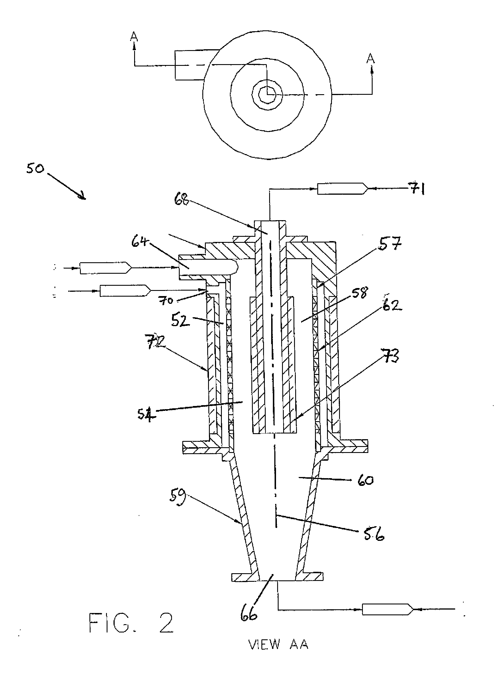
[0037]In use, the gas stream for treatment enters the contactor 50 through the inlet 70 and the chemical enters the contactor through the tangential inlet 64. The chemical swirls in the cyclone unit, i.e. the second chamber 54, and the gas swirls within the annulus, i.e. the first chamber 52, and is forced under pressure through the porous sintered tubular wall 62 into the cyclone unit, where it makes rapid contact with the chemical. As in the first embodiment, the ultrasonic transducers 72 emit ultrasonic noise which creates cavitation in the gas annulus and cyclone chamber to enhance the reaction between the chemical and gas to be treated. The ultra-sonic noise may be pulsed.

[0038]The gas is the lighter of the two phases, and migrates through the chemical and exits through the dip tube 68 and passes to an overflow outlet 71. The chemical, which is substantially de-gassed, reports to the cyclonic conical section 60, which acts as a back pressure and swirl accelerator within the uni...
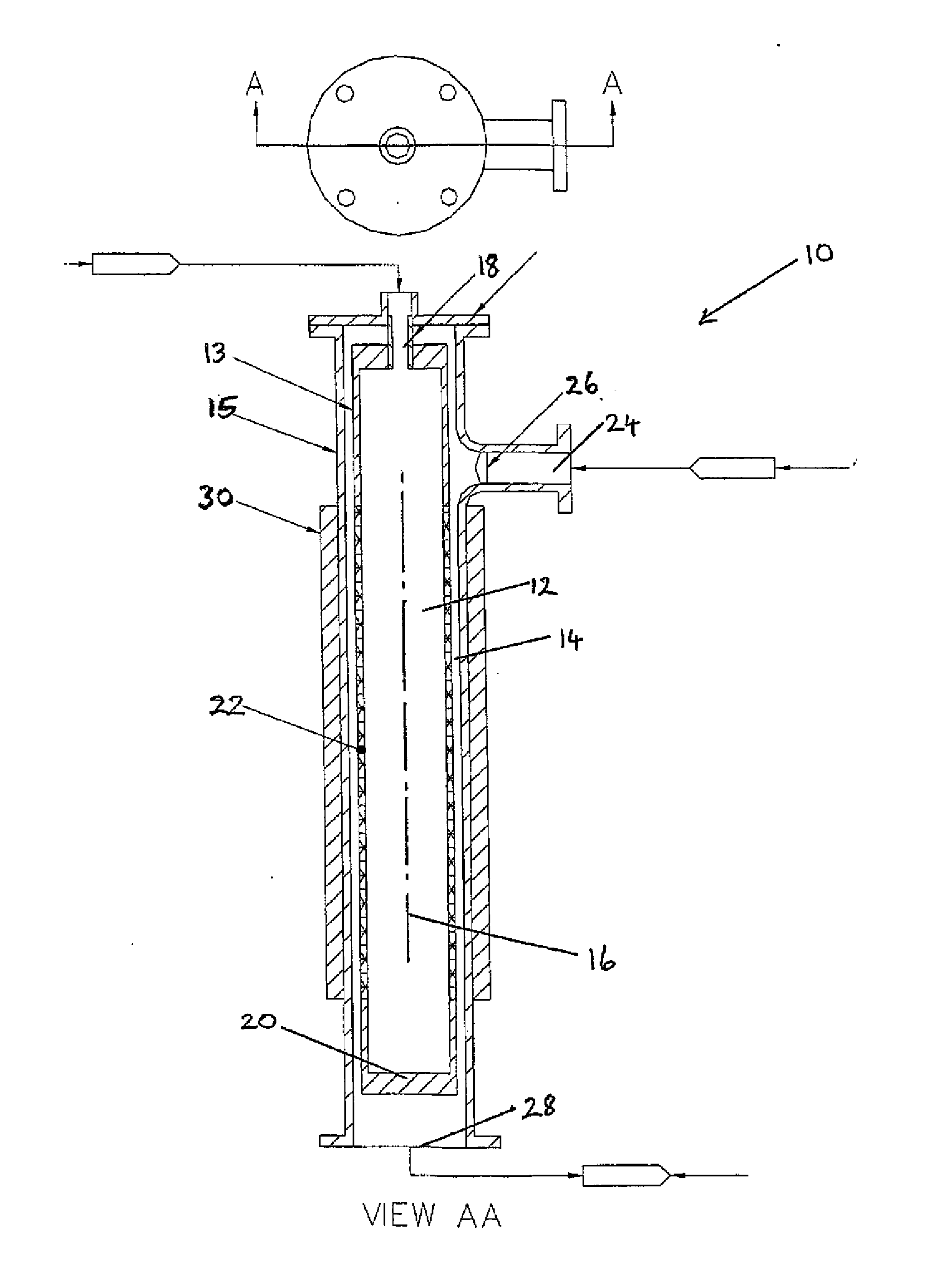
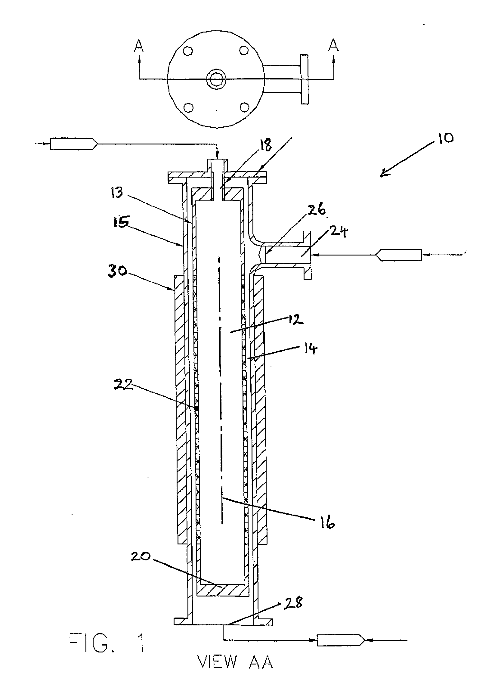
second embodiment

[0042]A significant advantage of the second embodiment described, is that a reaction vessel and cyclone unit are combined for the treatment of a fluid stream. Not only is the apparatus capable of reacting the gas and liquid reactants, but also can, at least partially, separate the different phases based on their specific gravity differential, after the reaction has taken place within the contactor. The manifold system described with reference to FIG. 3 allows use of a process in which flow down turn or unit duty standby is required, e.g. in the case of large fluctuating flow rates.


PUM

PropertyMeasurementUnit
pressureaaaaaaaaaa
temperatureaaaaaaaaaa
corrosionaaaaaaaaaa

Abstract

A contactor for reacting a flow of gas with a liquid, comprises a vessel, a first chamber in the vessel and a second chamber in the vessel, the first and second chambers being linked only by a porous wall, and means for directing ultrasonic noise into at least one of the first and second chambers.

Description

RELATED APPLICATIONS[0001]This application is a continuation of application Ser. No. 12 / 095,400 filed Jul. 22, 2009.BACKGROUND TO THE INVENTION[0002]The present invention relates to an apparatus and method for reacting a gas stream with a liquid, and more particularly to an improved gas-liquid contactor and method of operating the same.[0003]Natural gas can contain a number of non-hydrocarbon impurities both in the formation prior to extraction and / or following extraction at a wellhead. Some of these impurities are detrimental to efficient pipeline operation, whereas others have no effect on pipeline efficiency, but do affect the heat content or Btu rating of the natural gas.[0004]Nearly all natural gas contains some water vapor when extracted. The water vapor content in natural gas can be much lower than saturation, but is usually higher than that desired for satisfactory pipeline operation. The formation of free water in pipelines caused by pressure and / or temperature reduction ca...

Claims


Application Information

Patent Timeline
Patent Type & Authority Applications(United States)
IPC IPC(8): B01J10/00
CPCB01D53/18B01D53/78B01D2259/816B01J19/008B01J10/00B01J19/26B01J2219/0884C10L3/10C10L3/102B01J19/10B01J19/244B01F23/2133
Inventor DICKINSON, THEODORE E.PARKINSON, DAVID JOHNCOLLIER, KEVIN E.
Owner SPECIALIST PROCESS TECH
Why Eureka
Try Eureka