Cable connector

a cable connector and connector technology, applied in the direction of coupling device details, coupling device connections, electric discharge lamps, etc., to achieve the effect of more stable structure of the cable connector, reliable connection, and more stable electrical connection between the cable connector and an external circuit board

Inactive Publication Date: 2013-04-11
CHENG UEI PRECISION IND CO LTD
View PDF7 Cites 6 Cited by
  • Summary
  • Abstract
  • Description
  • Claims
  • Application Information

AI Technical Summary

Benefits of technology

[0006]As mentioned above, the first and second engaging parts are respectively engaged with the first and second coordinating protrusion at the front side and rear sides of the male base and the female base, hence the structure of the cable connector is more stable. Even if the cable is pulled up, the male base is not easy to depart from the female base, causing a more reliable connection therebetween. Therefore, the electrical connection between the cable connector and an external circuit board are more stable, thereby ensuring a reliable signal transmission.

Problems solved by technology

Even if the cable is pulled up, the male base is not easy to depart from the female base, causing a more reliable connection therebetween.

Method used


Image

  • Cable connector
  • Cable connector
  • Cable connector

Examples


Embodiment Construction

[0010]Reference will now be made in detail to the present preferred embodiment of the invention, example of which is illustrated in the accompanying drawings.

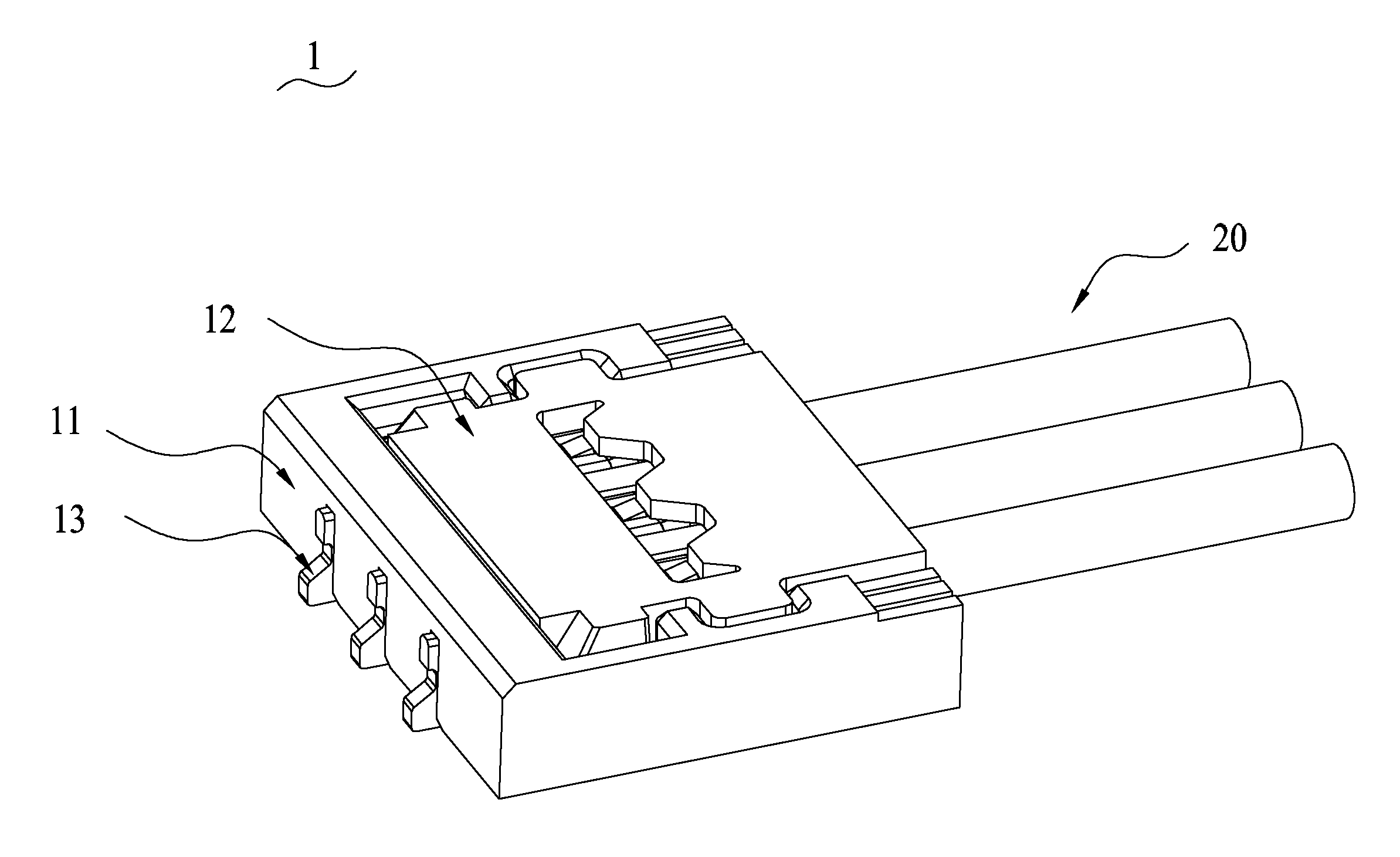
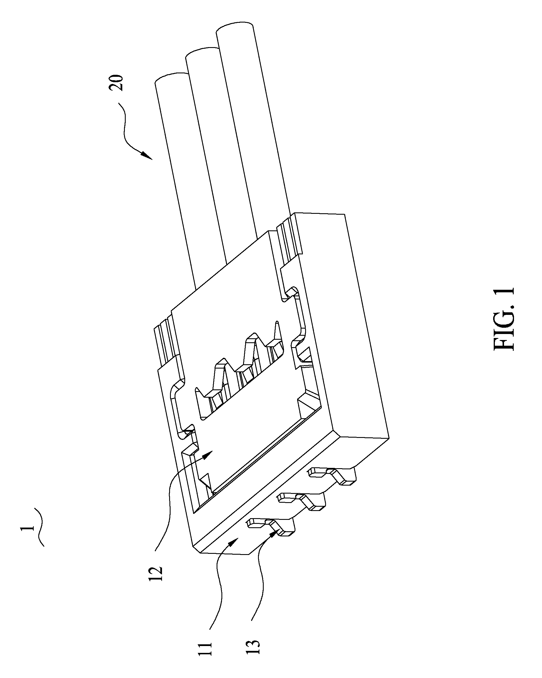
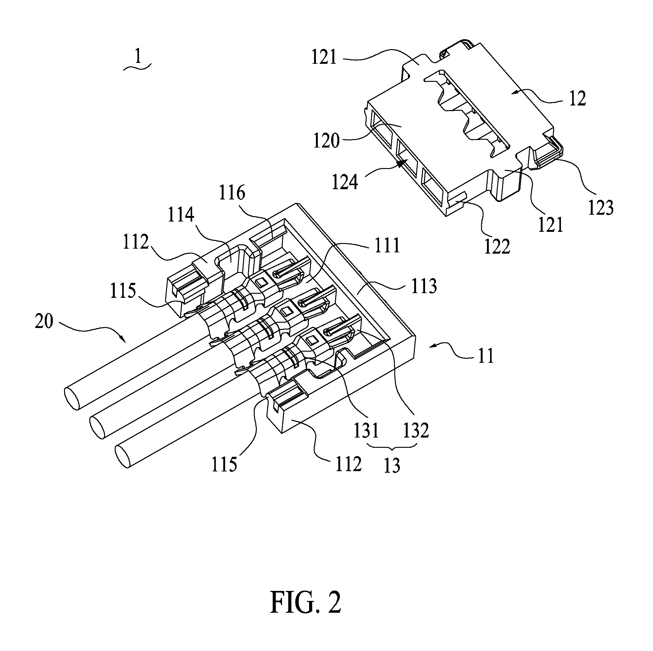
[0011]Referring to FIG. 1 to FIG. 3, a cable connector 1 of one embodiment of the present invention includes: a female base 11 being coupled to an external circuit board (not shown); a male base 12, which is coupled to the female base 11, having channels 124 for inserting cables 20, respectively; and a plurality of conductive terminals 13 being respectively coupled to the circuit board and the cables 20. The following detailed description refers to the structural stability of the connection between the female base 11 and the male base 12 of the cable connector 1 for the steady electrical connection between the cables 20 and the circuit board.

[0012]As shown in FIG. 2 and FIG. 3, the female base 11 is substantially square, and the female base 11 has a semi-enclosed receiving space (not shown). Moreover, a shape of the male base 1...


PUM


Abstract

Disclosed is a cable connector. The cable connector includes a female base coupled to a circuit board; a male base which is coupled to the female base has channels for inserting cables; and conductive terminals respectively coupled to the circuit board and the cables. The female base includes a bottom plate, two side walls, and a rear wall. A first engaging part and a second engaging part are respectively disposed at a front and a rear of the side walls. A first coordinating protrusion and a second coordinating protrusion are disposed at the male base respectively corresponding to the first engaging part and the second engaging part. The first engaging parts and the second engaging parts are respectively engaged with the first coordinating protrusions and the second coordinating protrusions. The cable connector of the present invention has a stable structure and a steady electrical connection.

Description

FIELD OF THE INVENTION[0001]The present invention relates to a connector, and especially to a cable connector.BACKGROUND OF THE INVENTION[0002]Cable connectors are widely used in network communication equipments. A cable connector is disposed on a circuit board for providing a space for inserting a cable, and the cable connector is utilized to achieve an electrical communication for the circuit board via conductive terminals thereof, so data transmission can be realized.[0003]A conventional cable connector generally includes a female base which is disposed on the circuit board and a male base which is coupled to the cable. The connection method that the female base and the male base coupled to each other is made by embedding. For example, a positioning protrusion is disposed at a side of the male base, and a positioning groove is disposed at the female base, in which the positioning protrusion is mated to the positioning groove. However, such structures are often not stable. The pos...

Claims


Application Information

Patent Timeline
Patent Type & Authority Applications(United States)
IPC IPC(8): H01R24/00
CPCH01R13/6271H01R12/75
Inventor CHIANG, CHIH-HSIEN
Owner CHENG UEI PRECISION IND CO LTD
Why Eureka
Try Eureka