Fuel tank installation

a technology for installing fuel tanks and fuel tanks, which is applied in the direction of water supply tanks, pumping plants, domestic plumbing, etc., can solve the problems of complex cooling arrangements and weakening of the lower cover of the wing, and achieve the reduction of assembly and maintenance time, quick and easy removal, and the effect of weight and part coun

Inactive Publication Date: 2013-04-18
AIRBUS OPERATIONS LTD
View PDF13 Cites 8 Cited by
  • Summary
  • Abstract
  • Description
  • Claims
  • Application Information

AI Technical Summary

Benefits of technology

[0012]The cage may be attached to the mounting piece by a bayonet type connection. Such a bayonet fitting allows the cage to be quickly and easily removed for inspection or maintenance of the pump assembly, and eliminates the need for mechanical fasteners. In this way assembly and maintenance time are reduced as well as the weight and part count of the installation.
[0013]The fuel tank installation may further comprise a

Problems solved by technology

However, it weakens the lower cover of the wing and necessitates local structural reinforcemen

Method used


Image

  • Fuel tank installation
  • Fuel tank installation
  • Fuel tank installation

Examples


Embodiment Construction

)

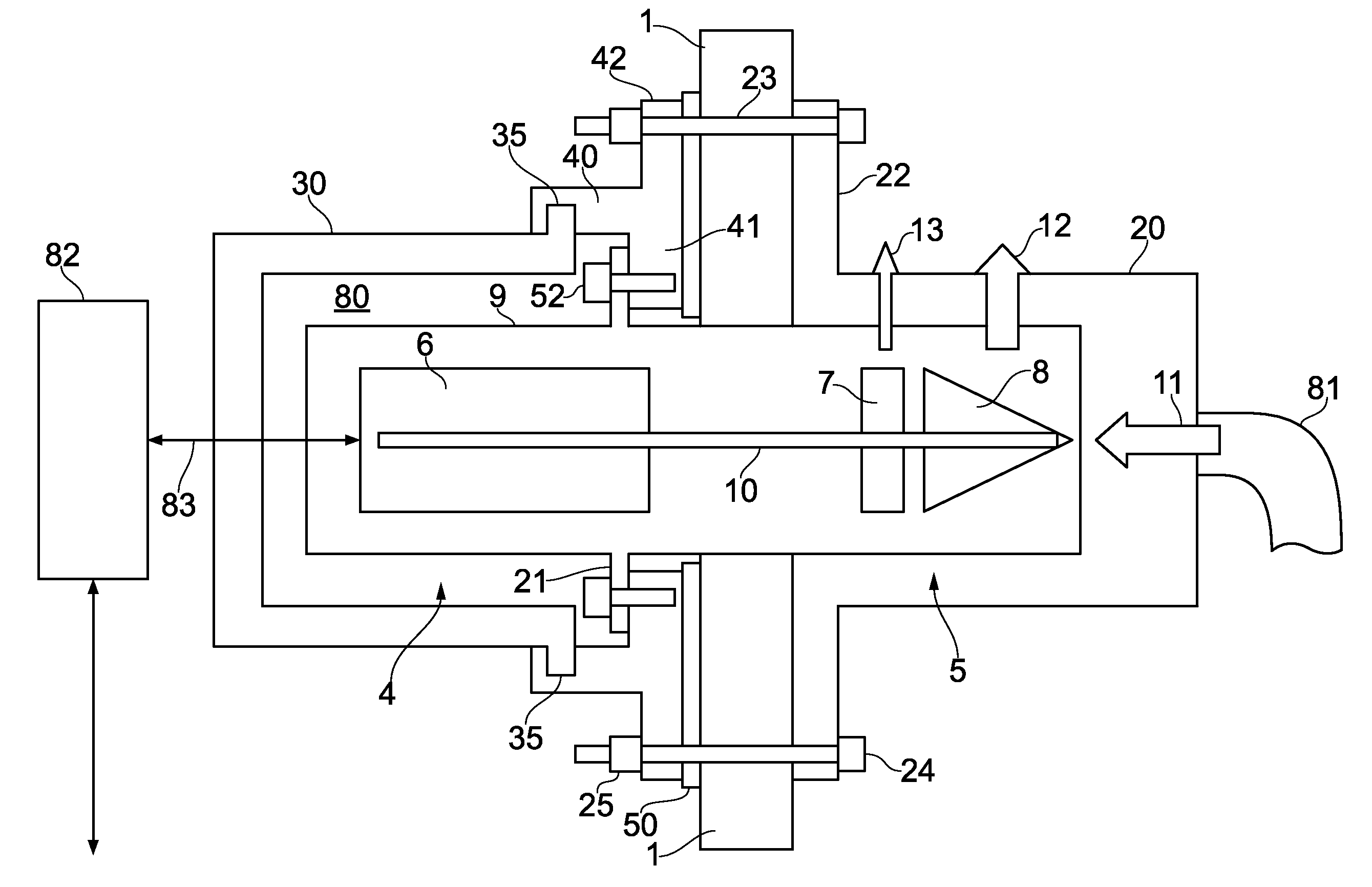
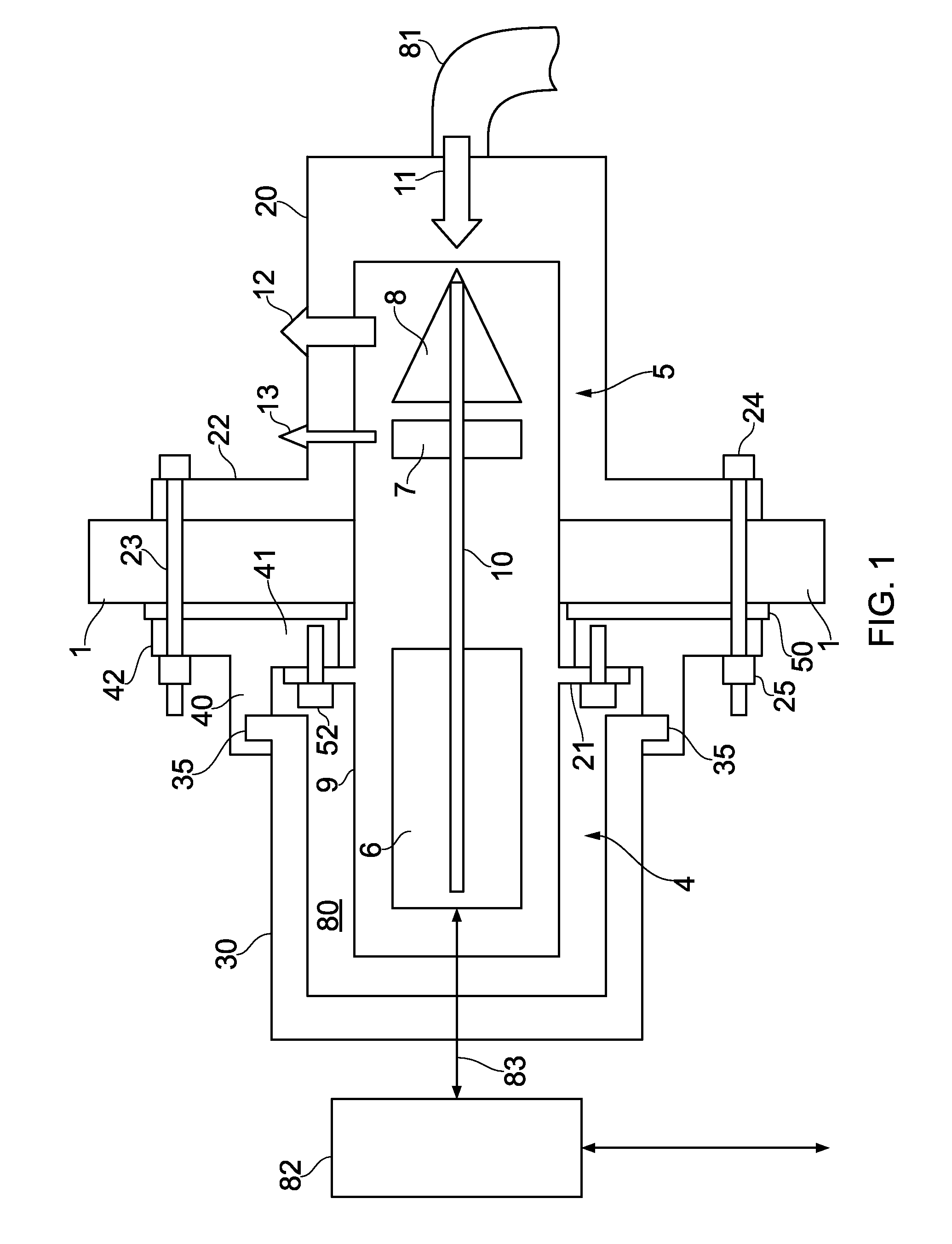
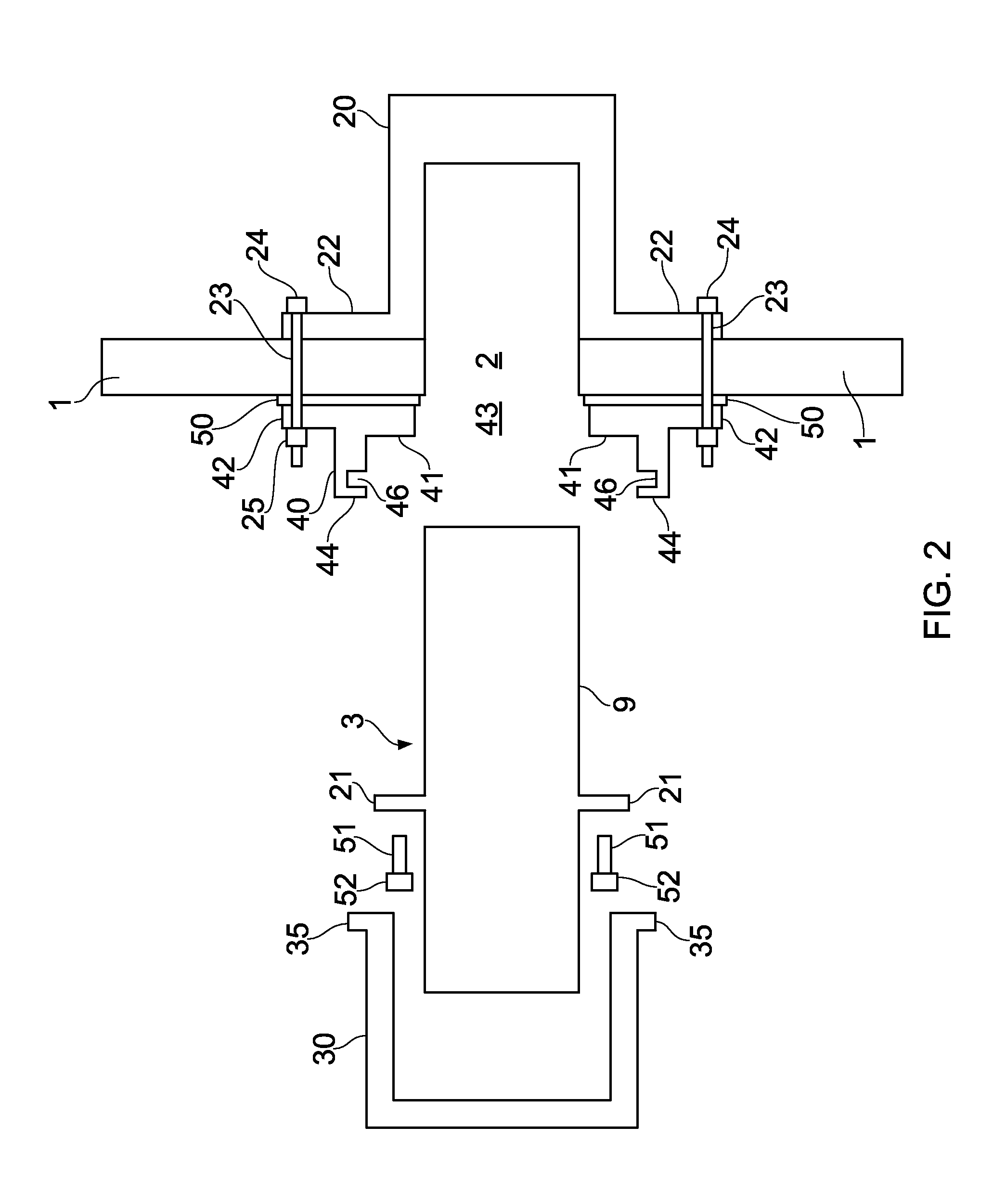
[0031]A fuel tank installation shown in FIG. 1 is formed from a kit of parts shown in FIG. 2. The installation comprises a fuel tank wall 1 formed with a hole 2 shown in FIG. 2. A fuel pump assembly 3 is fitted into the hole 2 as shown in FIG. 1 with an inner part 5 protruding to the right from an inner side of the hole 2 and an outer part 4 protruding to the left from an outer side of the hole 2.

[0032]The fuel pump assembly comprises a 7 kW electric motor 6 which is positioned outside (that is, to the left of) the outer side of the hole 2, and a pump 7, 8 which is positioned inside (that is, to the right of) the inner side of the hole 2. The pump comprises a ring impeller 7 and a main impeller 8 carried on a rotary shaft 10 which is rotated when in use by the electric motor 6.

[0033]The electric motor 6 and pump 7, 8 are housed within a casing 9 which engages the sides of the hole 2. The casing 9 has an inlet (not shown) for admitting fuel 11 into the pump from the fuel tank; a mai...


PUM


Abstract

A fuel tank installation comprising: a fuel tank for holding fuel, the fuel tank comprising a fuel tank wall formed with a hole; a fuel pump assembly fitted into the hole in the fuel tank wall with an inner part of the fuel pump assembly protruding from an inner side of the hole and an outer part of the fuel pump assembly protruding from an outer side of the hole; a cage surrounding the outer part of the fuel pump assembly; and a mounting piece which attaches both the cage and the fuel pump assembly to the fuel tank wall.

Description

FIELD OF THE INVENTION[0001]The present invention relates to a fuel tank installation comprising a fuel tank and a fuel pump assembly.BACKGROUND OF THE INVENTION[0002]Fuel pump assemblies are commonly used in aircraft fuel systems to transfer fuel from one fuel tank to another and to supply engines with a stream of fuel. Such fuel pump assemblies are commonly mounted on the lower cover of a wing, as shown in WO2007 / 071908. In this known arrangement the pump assembly is located within a fuel filled canister mounted on the inside of the wing cover.[0003]This arrangement allows the pump assembly to be well protected within the fuel tank region between the wing covers. However, it weakens the lower cover of the wing and necessitates local structural reinforcement. Also, a complex cooling arrangement is required to cool the electric motor and pumping unit.SUMMARY OF THE INVENTION[0004]A first aspect of the present invention provides a fuel tank installation comprising: a fuel tank wall f...

Claims


Application Information

Patent Timeline
IPC IPC(8): B60K15/077
CPCY02T50/44B64D37/005B64D37/10Y02T50/40Y10T137/6906Y10T137/85978Y10T137/86035
Inventor LEIGHTON, DAVID
Owner AIRBUS OPERATIONS LTD
Why Eureka
Try Eureka