Apparatus and method for estimating wavefront parameters

a technology of optical wavefront and approximation method, applied in the direction of optical radiation measurement, photometry using reference value, instruments, etc., can solve the problems of introducing system aberration, unable to analyze the wavefront of sensor array shwf, and the fabrication cost of a null lens can become prohibitively expensiv

Active Publication Date: 2013-04-18
CANON KK +1
View PDF32 Cites 37 Cited by
  • Summary
  • Abstract
  • Description
  • Claims
  • Application Information

AI Technical Summary

Problems solved by technology

However, dividing the original beam and recombining it with the reference beam tends to introduce system aberrations, for example due to optical-path errors and improper alignment of optical components.
However, if the wavefront deviation exceeds the dynamic range of the SHWFS, as illustrated in FIG. 3, the sensor array SHWFS cannot analyze the wavefront anymore.
Therefore, the fabrication cost of a null lens can become prohibitively expensive.
Furthermore, such a null lens is designed for specific test optics with an expected wavefront aberration, thus this technique may be not applicable to other wavefronts formed by test optics of different shapes or characteristics.
However, those of ordinary skill in the art should readily appreciate that performing a series of wavefront measurements and stitching those measurements together using mathematical methods is a computing-intensive process.

Method used


Image

  • Apparatus and method for estimating wavefront parameters
  • Apparatus and method for estimating wavefront parameters
  • Apparatus and method for estimating wavefront parameters

Examples


second embodiment

[0103]In the present invention, a solution to the problem of optimized parameters converging towards local minima different from true target values is proposed, so that accuracy of the estimation is improved.

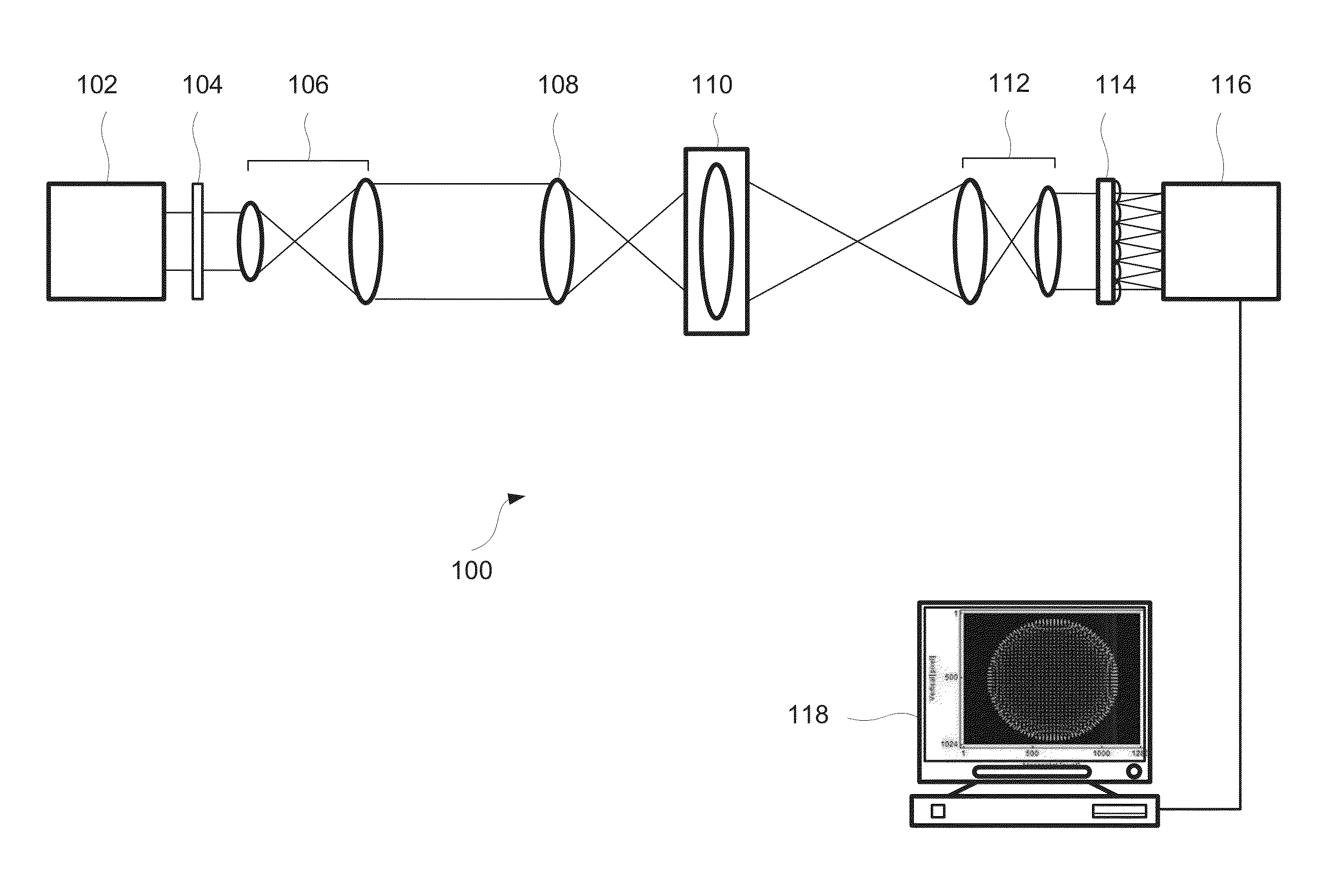
[0104]FIG. 13 illustrates the configuration of a wavefront measurement apparatus 1111, in accordance with the second embodiment of the present invention. The wavefront measuring apparatus 1111 includes a light source 1100, wavefront sensor 1115 and a data analyzer 1118. The light source 1100 emits a light beam B, the light beam passes through filtering optics 1101 (e.g., ND filter), is shaped by illumination optics 1102; and then the shaped beam illuminates a test element 1103. The test element 1103 can be a single optical element, such as a lens, prism, waveguide or the like, or it can be a combination of optical elements. In order to compensate (reduce) wavefront aberrations introduced by the test element 1103, a corrective element 504 (as described in the first embodiment) ca...

first embodiment

[0164]The fitting process for {C2, C7}, {C3, C8}, {C4, C9}, and {C5, C6} are executed at steps S2706 through S2709. After the fitting process, contracting-grid searches over parameter combinations {C2, C3}, {C4, C9}, {C5, C6}, {C2, C7}, {C3, C8}, and {C9, C16} are executed at steps S2710 through S2715. At step S2716, a determination is made as to whether a desired number of iterations N has been completed. When the number of iterations has not been completed the contracting-grid local search is repeated. When the number of iterations has been completed, the estimated values are output at step S2716. This improved process described in FIG. 30 can be applied to the first embodiment above within the back-propagation calculation.

[0165]The differences between estimated Zernike coefficients and target coefficients during the ML estimation using the fitting method are shown in FIG. 31. From this result, differences between target coefficients and estimated ones can become less than 0.1λ. T...


PUM


Abstract

An apparatus for estimating a wavefront parameter includes a light source, a lenslet array, a detector for detecting light generated by the light source and passed through the lenslet array, a wavefront corrective element disposed between the lenslet array and the light source; and a data analyzer configured to estimate at least one wavefront parameter at a plane located on the light source side of the corrective element. The lenslet array and the sensor array are arranged to form a wavefront sensor, and the wavefront corrective element is configured to correct an aberration of the wavefront.

Description

CROSS REFERENCE TO RELATED APPLICATIONS[0001]This application claims priority from Provisional Application No. 61 / 547,583 filed Oct. 14, 2011, the disclosure of which is hereby incorporated by reference herein in its entirety.BACKGROUND OF THE INVENTION[0002]1. Field of the Invention[0003]The present invention relates to an apparatus and a method for estimating optical wavefront parameters, such as wavefront shape and aberration.[0004]2. Description of the Related Art[0005]Wavefront measurements are typically used to test the quality of optical surfaces and evaluate optical performance of optical elements. Wavefront measurements are also used for alignment of high-accuracy optical systems. A wavefront is the locus (a line, or in a wave propagating in 3 dimensions, a surface) of points on which all light rays have the same phase. The simplest form of a wavefront is that of a plane wave, where rays of light are parallel to each other and strike a sensor with a planar wavefront. Propag...

Claims


Application Information

Patent Timeline
Patent Type & Authority Applications(United States)
IPC IPC(8): G01J1/20
CPCG01J9/00
Inventor BARRETT, HARRISONCAUCCI, LUCAFURENLID, LARSOHKUBO, AKINORI
Owner CANON KK
Why Eureka
Try Eureka