Electronic device and electronic device assembly thereof

a technology of electronic devices and tandem connections, which is applied in the direction of coupling device connections, fixed connections, electrical apparatus contruction details, etc., can solve the problems of unaddressed need in the art, multiple electronic devices cannot be directly connected in series through thunderbolt, and complex structures among apparatuses, so as to save the space occupied by connecting cables and reduce the cost

Inactive Publication Date: 2013-04-18
LINTES TECH
View PDF5 Cites 2 Cited by
  • Summary
  • Abstract
  • Description
  • Claims
  • Application Information

AI Technical Summary

Benefits of technology

[0024]Compared with the related art, among other things, in an electronic device with a tandem connection function according to the present invention, a male connector and a female connector matching with each other are disposed, so that multiple electronic devices having different functions are directly joined two by two through the male and female connectors without having to further connecting each electronic device, which not only implements multifunctional applications but also saves the space occupied by connecting cables, thereby lowering the cost. In addition, the two circuit boards are connected through a flexible circuit board. Due to the flexibility of the flexible circuit board, different distances may be designed between two circuit boards according to demands to meet different thickness requirements of electronic devices.

Problems solved by technology

For example, an SCSI, an SATA, a USB, FireWire, a PCI Express and the like are disposed on a computer so that apparatuses must be connected through external connection cables of different specifications, causing complex structures among apparatuses.
However, as multiple thunderbolt connectors disposed on an electronic device are socket connectors, and these socket connectors are located at the same side of the electronic device, making the two electronic devices can only be connected through a transmission cable with a thunderbolt plug connector at both ends, so that multiple electronic devices cannot be directly connected in series through thunderbolt connectors.
Therefore, a heretofore unaddressed need exists in the art to address the aforementioned deficiencies and inadequacies.

Method used


Image

  • Electronic device and electronic device assembly thereof
  • Electronic device and electronic device assembly thereof
  • Electronic device and electronic device assembly thereof

Examples


Embodiment Construction

[0032]The present invention is more particularly described in the following examples that are intended as illustrative only since numerous modifications and variations therein will be apparent to those skilled in the art. Various embodiments of the invention are now described in detail. Referring to the drawings, like numbers indicate like components throughout the views. As used in the description herein and throughout the claims that follow, the meaning of “a”, “an”, and “the” includes plural reference unless the context clearly dictates otherwise. Also, as used in the description herein and throughout the claims that follow, the meaning of “in” includes “in” and “on” unless the context clearly dictates otherwise. Moreover, titles or subtitles may be used in the specification for the convenience of a reader, which shall have no influence on the scope of the present invention.

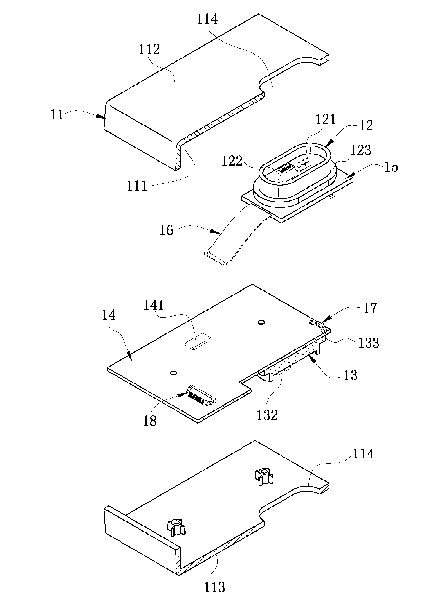
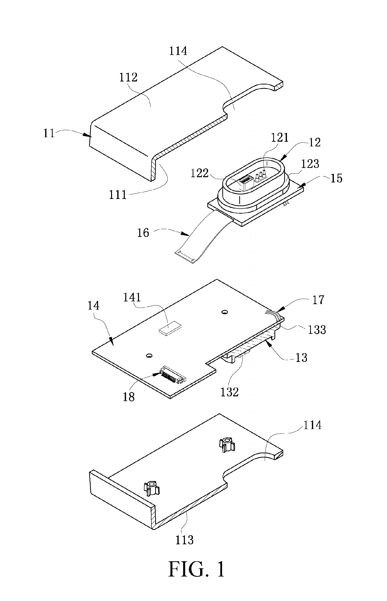
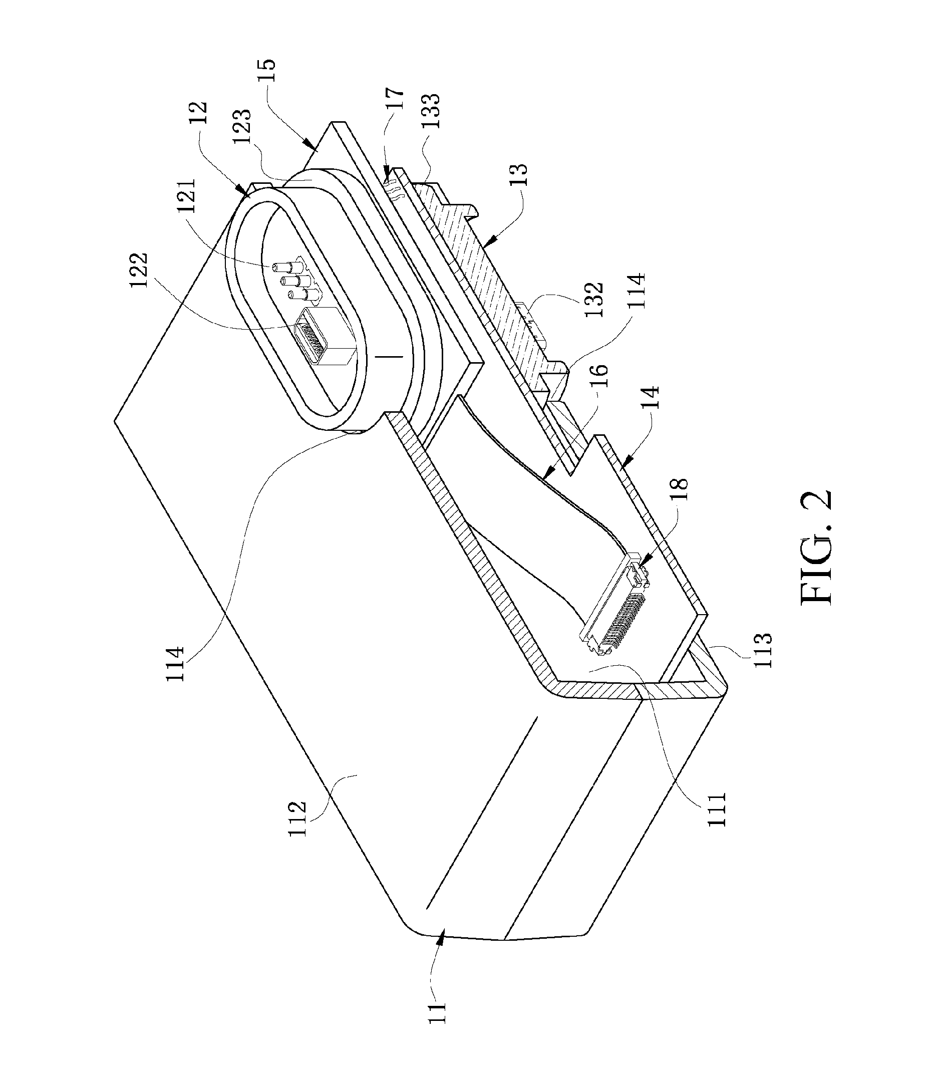
[0033]FIGS. 3 and 4 show an electronic device with a tandem connection function and an electronic device as...


PUM


Abstract

An electronic device assembly includes at least two electronic devices. Each electronic device has a body, two circuit boards and a flexible circuit board. A male connector and a female connector are installed at the positions corresponding to two ends of the body respectively, and the male and female connectors matching with each other in terms of specification. The two circuit boards are disposed at the two ends of the body respectively, and the two circuit boards are located between the male and female connectors and connected to the male and female connectors respectively. The two circuit boards are connected through the flexible circuit board to electrically connect the male and female connectors, in which the male connector of one electronic device and the female connector of the other electronic device are joined.

Description

CROSS-REFERENCE TO RELATED APPLICATIONS[0001]This application claims priority to and the benefit of, pursuant to 35 U.S.C. §119(e), U.S. provisional patent application Ser. No. 61 / 547,269, filed Oct. 14, 2011, entitled “Docking Member,” by Wei Zen Lo, the disclosure of which is incorporated herein in its entirety by reference.[0002]Some references, if any, which may include patents, patent applications and various publications, may be cited and discussed in the description of this invention. The citation and / or discussion of such references, if any, is provided merely to clarify the description of the present invention and is not an admission that any such reference is “prior art” to the invention described herein. All references listed, cited and / or discussed in this specification are incorporated herein by reference in their entireties and to the same extent as if each reference was individually incorporated by reference.FIELD OF THE INVENTION[0003]The present invention relates ge...

Claims


Application Information

Patent Timeline
Patent Type & Authority Applications(United States)
IPC IPC(8): H05K7/10
CPCH05K1/147H05K2201/10189H01R13/6658H01R12/52H01R12/62H05K2201/10356
Inventor LO, WEI-ZEN
Owner LINTES TECH
Why Eureka
Try Eureka