Dual band antenna with circular polarization

Inactive Publication Date: 2013-10-31
NAT TAIWAN UNIV OF SCI & TECH
View PDF44 Cites 1 Cited by
  • Summary
  • Abstract
  • Description
  • Claims
  • Application Information

AI Technical Summary

Benefits of technology

The invention is a dual band antenna with circular polarization. It achieves this by using a vacant area on a substrate and a meandering structure on a radiation metal portion. The antenna is designed to have better impedance match and radiation efficiency for circularly polarized signals. It also aims to save space on handheld devices by providing a compact size and design.

Problems solved by technology

However, the generally circular polarized antenna in current market is usually occupied a great volume of space in hand-held navigation and positioning device, or use more expensive high-dielectric substrate to shrink its size.
The common antenna having built-in and polarization characteristics, most of them are expensive ceramic patch antenna or external cantilevered spiral antenna, its advantages are free from the influence of the use of space, but do not have dual-band operating results.
Therefore, if it want to increase its operating band, it must add the additional antenna or changes in architecture, thus it is disadvantageous to the built-in handheld navigation and positioning device.

Method used


Image

  • Dual band antenna with circular polarization
  • Dual band antenna with circular polarization
  • Dual band antenna with circular polarization

Examples


first embodiment

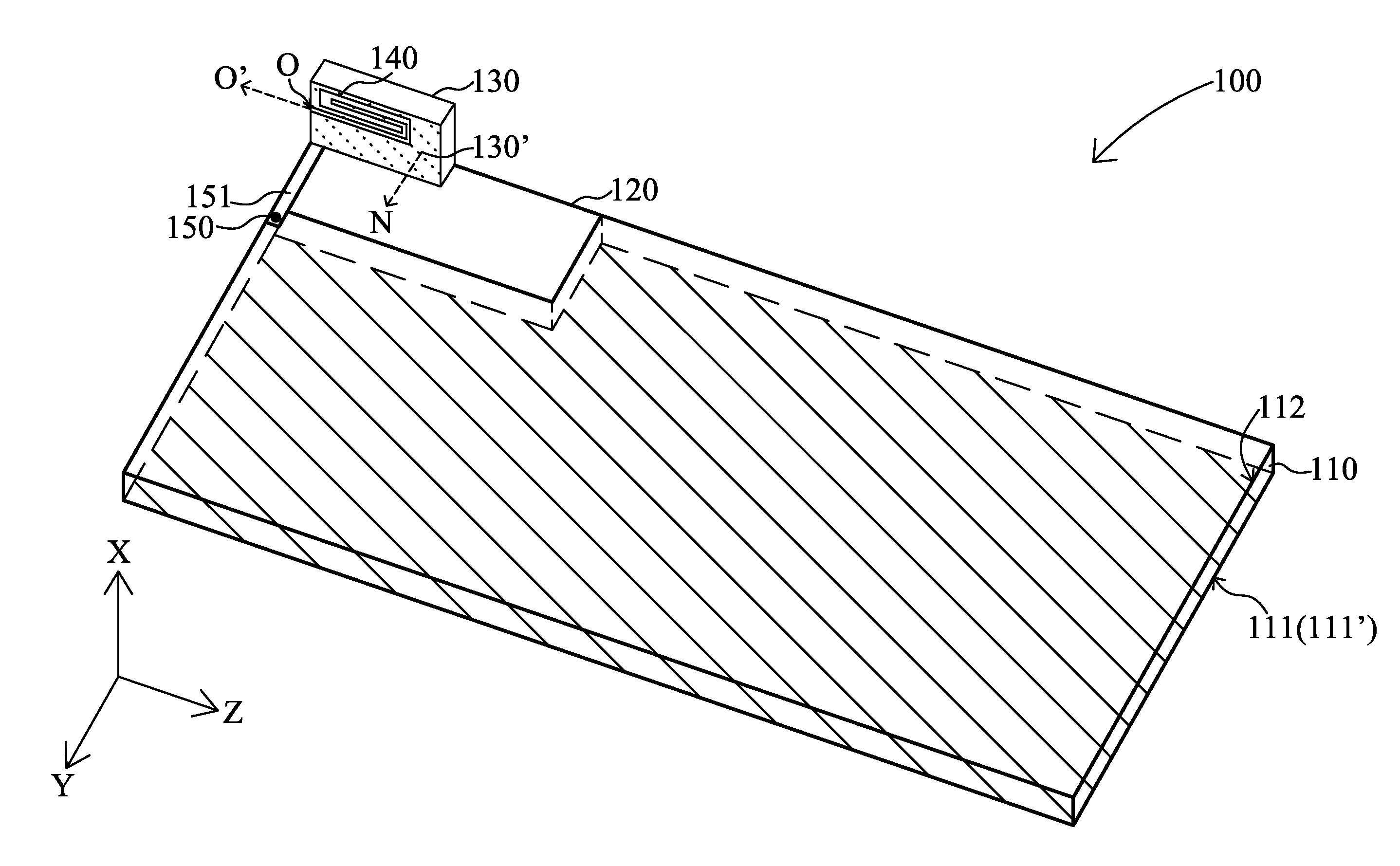
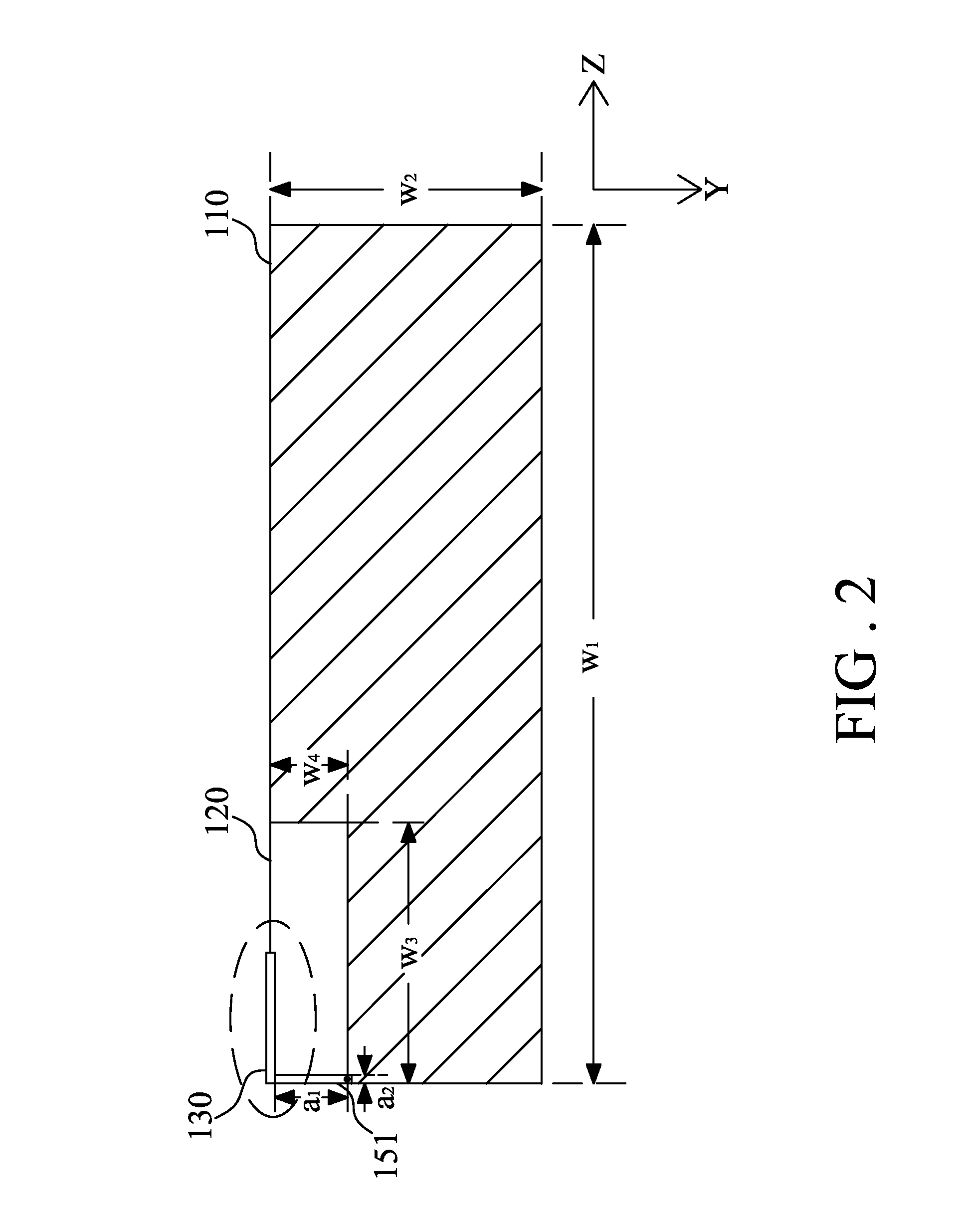
[0028]FIG. 2A is a side enlarged schematic of the radiation metal portion 130 in FIG. 2. The meandering structure 140 is disposed by the side of the radiation metal portion 130 and meandered in the shape of a paper clip. The meandering structure 140 includes a first line segment l1, a second line segment l3, a third line segment l5, a first connecting segment l2 and a second connecting segment l4. The first line segment l1, the second line segment l3 and the third line segment l5 are mutually parallel. And the first line segment l1 and the second line segment l3 are interconnected with the first connecting segment l2. The second line segment l3 and the third line segment l5 are interconnected with the second connecting segment l4. The third line segment l5 is disposed between the first line segment l1 and the second line segment l3. The meandering structure 140 has a slit 141. The slit 141 is meandered along with the meandering direction of the meandering structure 140 and forms an ...

second embodiment

[0033]Refer to FIG. 2B, is a side enlarged schematic of a radiation metal portion in FIG. 2. The meandering structure 140 is disposed on the radiation metal portion 130, slightly right edge of the upper side relative to the substrate 110. The opening direction O′ of the opening O on the meandering structure 140 is parallel to the first long side w1 of the substrate 110. The opening direction O′ is toward inside the substrate 110, and make the meandering structure 140 meandered in a clockwise direction L to form a paper clip shape, so as to enable the dual band antenna with circular polarization 100 to be used for the left rotation polarized.

[0034]According to the above embodiment, the current direction of the dual band antenna with circular polarization 100 may be operated effectively, by the designed meandering structure 140 on the radiation metal portion 130, then achieving the purpose of circular polarization. Besides, circular-polarization operation make use of the meandering st...


PUM


Abstract

A dual band antenna with circular polarization is applied in a handheld device and includes a substrate, a radiation metal portion and a feed-in stripline. The substrate has a vacant area and a feed-in point. The feed-in point is disposed near and outside the vacant area. The radiation metal portion is disposed vertically to a surface of the substrate at the edge of the vacant area, and includes a radiation surface and a meandering structure. The radiation surface is disposed at one side of the radiation metal portion and near the substrate. The meandering structure is disposed at another side of the radiation metal portion and far from the substrate. The feed-in stripline is disposed on the substrate. One end of the feed-in stripline is electrically connected to the feed-in point, and the other end of the feed-in stripline is electrically connected to the radiation metal portion.

Description

BACKGROUND OF THE INVENTION[0001](1) Field of the Invention[0002]The invention relates to a dual band antenna with circular polarization, and especially relates to a dual band antenna with circular polarization for handheld navigation and positioning apparatus having Global Positioning System (GPS).[0003](2) Description of the Prior Art[0004]The Global Positioning System (GPS) navigation and positioning device is the rapid development of products in the past decade, thus, making it a considerable scale and complete product line in market. In addition to the U.S. Global Positioning System (GPS) system, the other also include: bands such as E5a band (1.176 GHz), E5b band (1.207 GHz), E6-band (1.278 GHz) and E1 band (1.575 GHz) of the European Union Galileo positioning system; and bands such as band L1 (1.602 GHz) and band L2 (1.246 GHz) of Russia's global Navigation Satellite System (GLONASS); and bands such as band E1 (1.589 GHz), band E2 (1.561 GHz), band E6 (1.268 GHz) and band E5b...

Claims


Application Information

Patent Timeline
IPC IPC(8): H01Q5/01H01Q5/10H01Q5/15
CPCH01Q5/01H01Q5/371H01Q1/36
Inventor CHANG, SHIH-HSUNLIAO, WEN-JIAO
Owner NAT TAIWAN UNIV OF SCI & TECH
Why Eureka
Try Eureka