

Backlight module and LCD comprising the same
- Summary
- Abstract
- Description
- Claims
- Application Information
AI Technical Summary
Benefits of technology
Problems solved by technology
Method used
Image

Examples
Embodiment Construction
[0026]It shall be understood that, the embodiments described herein are only intended to illustrate but not to limit the present disclosure.
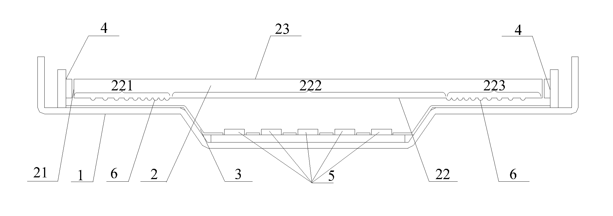
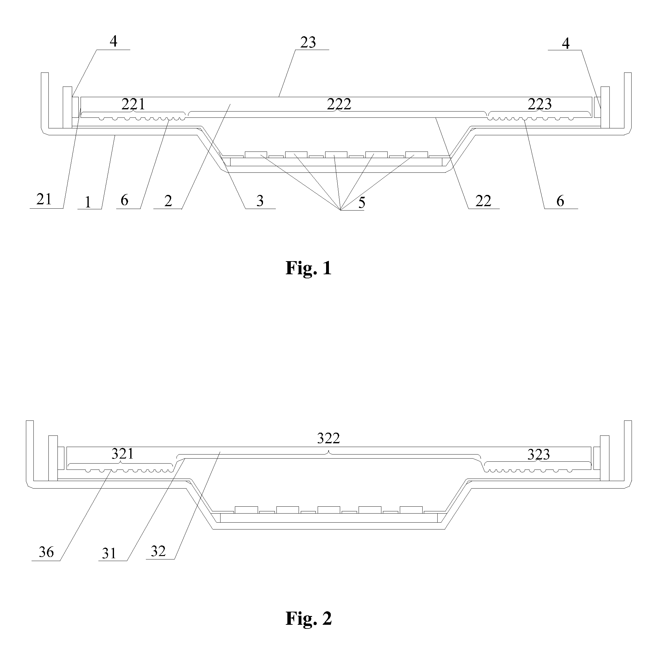
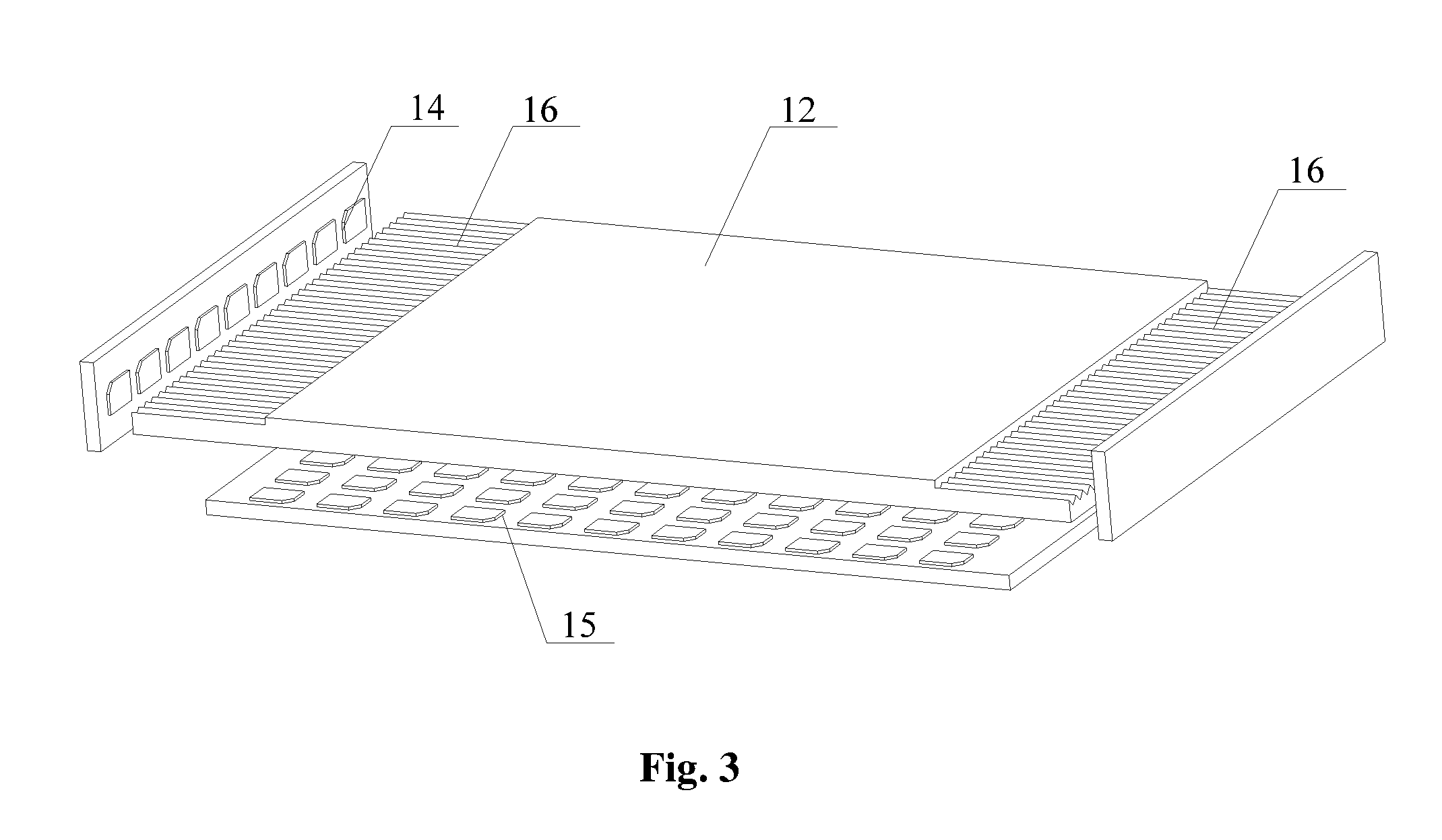
[0027]Embodiments of the present disclosure mainly adopt the following solution: the direct-lit design and the edge-lit design are used in combination in the backlight module, and a number of light scattering structures for scattering light rays are disposed on a light exiting surface or a bottom surface of the light guide panel at both ends of the light guide panel to divide the light guide panel into three backlight regions. Regions illuminated by the backlight from the edge-lit LED arrays are controlled by the light scattering structures on the light guide panel while a region illuminated by the backlight from the direct-lit LED array is controlled by the LED drive circuit. In this way, the effect of adjusting the brightness of the backlight of the backlight module region by region is improved and the power consumption of the liquid crystal m...
PUM
 Abstract
Description
Claims
Application Information