
System and Method for Exchangeable Capacitor Modules for High Power Inverters and Converters

a technology of capacitor modules and converters, applied in capacitor testing, power supply testing, instruments, etc., can solve the problems of capacitors eventually dying out, their performance is dramatically reduced, and end up not lasting very long, and achieve the effect of facilitating notification

Active Publication Date: 2013-04-18
NEWLIGHT CAPITAL LLC
View PDF3 Cites 134 Cited by
  • Summary
  • Abstract
  • Description
  • Claims
  • Application Information

AI Technical Summary

Benefits of technology

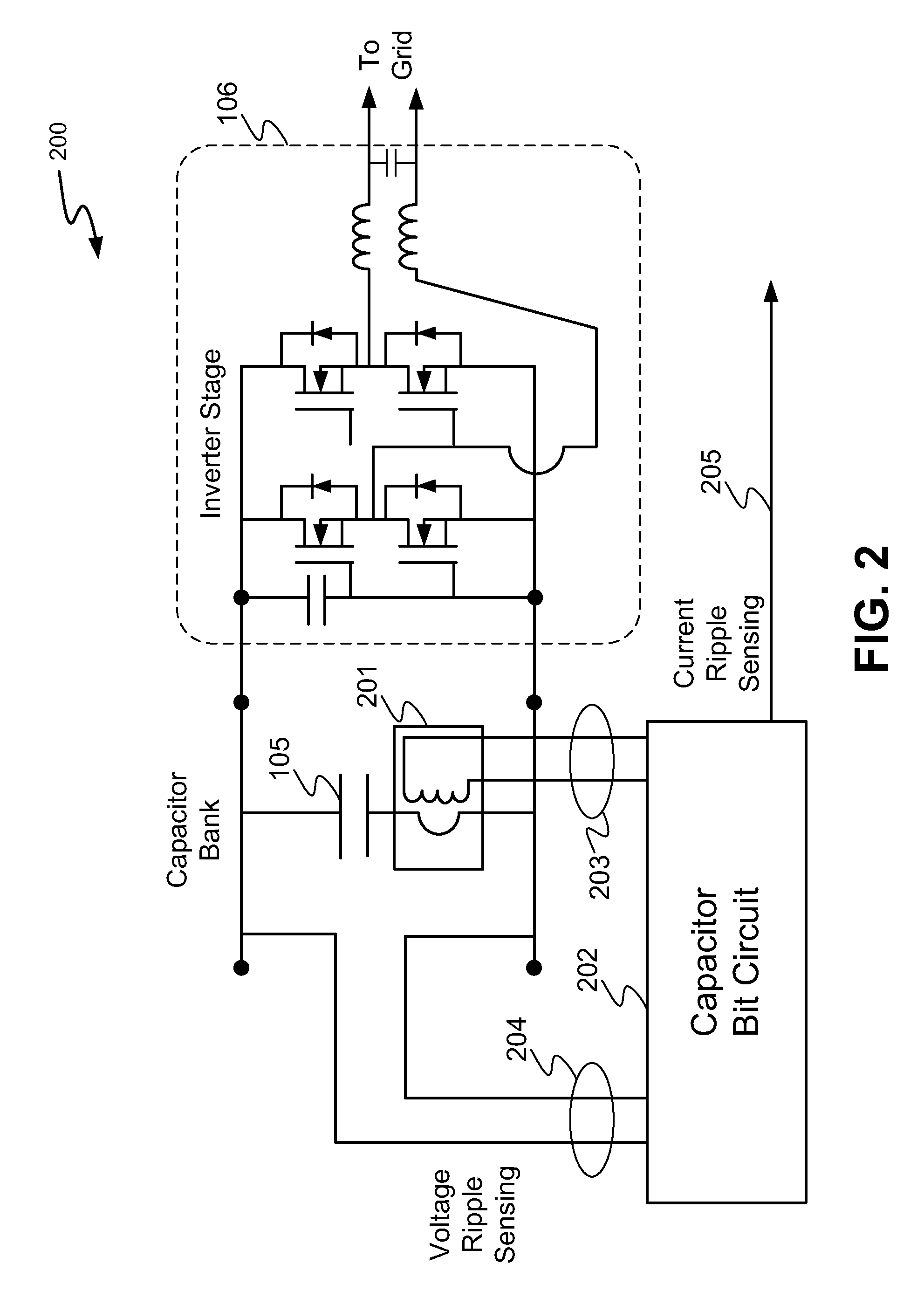
The present invention is about monitoring the condition of a capacitor in a power inverter circuit. Specifically, the invention relates to measuring the ripple voltage and current in the capacitor and determining if they exceed a predetermined threshold. This information is then sent to a controller or a health monitoring system, which can schedule maintenance on the capacitor if necessary. The invention also includes a sensor that can measure the temperature of the capacitor. The monitoring circuit uses a microprocessor programmed to analyze the ripple voltage and current, compare them to a predetermined threshold, and issue an output signal if they exceed the threshold. Overall, the invention provides a more efficient and effective way to prevent failure of the capacitor in the power inverter circuit.

Problems solved by technology

Many converters are often out in the field, exposed to the elements, and at times in a very hot or very cold environment.
Because they contain electrolytic capacitors, in particular, large electrolytic capacitors to support some internal high-voltage dc bus, they often end up not lasting very long because the capacitors die prematurely even if the remainder of the circuitry is good.
In some cases, the capacitor may not completely die, but it may degrade to a point where its performance is reduced dramatically, so that eventually it shuts off for safety reasons.
The same problem occurs in the power supplies of computers and other electronic equipment, wherein the capacitors eventually die out.

Method used


Image

  • System and Method for Exchangeable Capacitor Modules for High Power Inverters and Converters
  • System and Method for Exchangeable Capacitor Modules for High Power Inverters and Converters
  • System and Method for Exchangeable Capacitor Modules for High Power Inverters and Converters

Examples


Embodiment Construction

[0019]The following description and drawings are illustrative and are not to be construed as limiting. Numerous specific details are described to provide a thorough understanding. However, in certain instances, well known or conventional details are not described in order to avoid obscuring the description. References to one or an embodiment in the present disclosure are not necessarily references to the same embodiment; and, such references mean at least one.

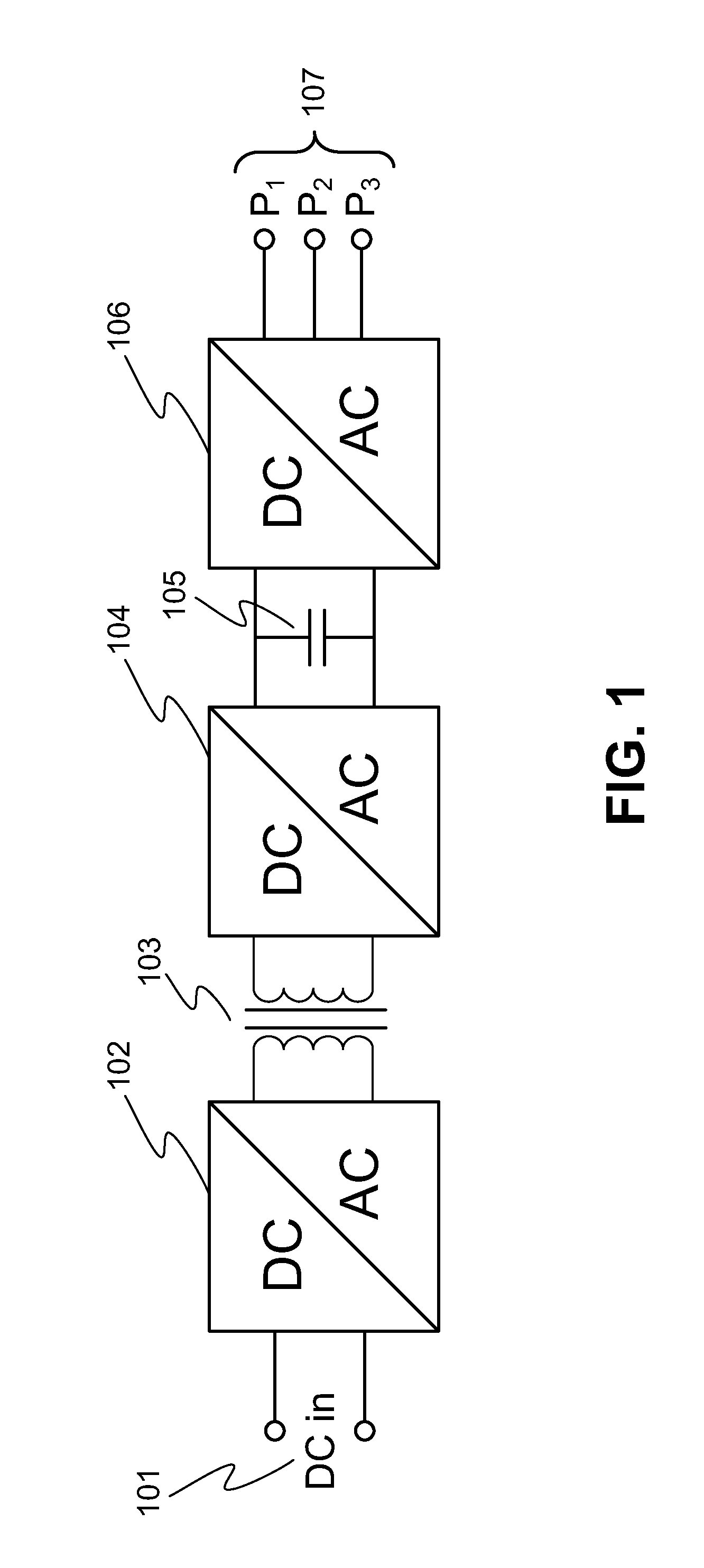
[0020]FIG. 1 shows an overview of a power inverter 100 in accordance with the present disclosure. An initial circuitry 102, typically referred to as a chopper, takes in the DC power from the source 101 and converts the power to radio frequency (RF) power. The size and weight and cost of transformers typically shrinks in accordance with T=1 / square of the frequency. Thus, the higher the frequency, the smaller the transformer. However, this is counterbalanced by switching losses, that increase with frequency, and so, for each syst...


PUM


Abstract

A method of and system for monitoring condition of a large capacitor connected across an output of a rectifier circuit in an operating electrical power transmission circuit in order to anticipate capacitor failure and facilitate appropriate corrective action is disclosed. The method includes measuring a ripple voltage on the capacitor and ripple current through the capacitor, determining from a representative signal whether the signal exceeds a predetermined threshold; and sending an output to a controller on a system operator if the signal exceeds the predetermined threshold. The ripple current and ripple voltage measurements may be provided as inputs to a digital to analog converter which produces and sends the representative signal to a microprocessor to generate the output to the controller.

Description

CROSS REFERENCE TO RELATED APPLICATIONS[0001]This application claims the benefit of priority of U.S. Provisional Patent Application Ser. No. 61 / 548,674 filed Oct. 18, 2011, which is incorporated herein by reference in its entirety.FIELD OF THE TECHNOLOGY[0002]This disclosure relates generally to high power electrical transmission systems and more particularly to high power inverters and converters employing electrolytic capacitors.BACKGROUND[0003]Many converters are often out in the field, exposed to the elements, and at times in a very hot or very cold environment. Because they contain electrolytic capacitors, in particular, large electrolytic capacitors to support some internal high-voltage dc bus, they often end up not lasting very long because the capacitors die prematurely even if the remainder of the circuitry is good. In some cases, the capacitor may not completely die, but it may degrade to a point where its performance is reduced dramatically, so that eventually it shuts of...

Claims


Application Information

Patent Timeline
IPC IPC(8): H02M7/5387H02M7/02
CPCG01R31/028H02M1/32G01R31/42H02M7/4807H02M7/04G01R31/64
Inventor AVRUTSKY, MORDECHAY
Owner NEWLIGHT CAPITAL LLC
Learn More