Transponder with receiving means having a low electrical consumption in a listening mode

a transponder and listening mode technology, applied in the field of transponders, can solve the problems of low sensitivity of the passive envelope detector itself, relatively large electric power consumption of the amplifier, and low sensitivity of the transponder

Active Publication Date: 2013-04-18
SMARTRAC TECH WEHNRATH +1
View PDF5 Cites 49 Cited by
  • Summary
  • Abstract
  • Description
  • Claims
  • Application Information

AI Technical Summary

Benefits of technology

[0019]In a particular embodiment, the wake-up circuit further controls the activation of a decoder and of a pattern correlator.

Problems solved by technology

Such an amplifier has relatively large electric power consumption and will also amplify interference signals received by the transponder with a modulation frequency closed to the predefined one for this transponder.
However, there are other problems which remains, in particular a sensitivity problem for the transponder.
Secondly, this passive envelope detector itself has a low sensitivity.

Method used


Image

  • Transponder with receiving means having a low electrical consumption in a listening mode
  • Transponder with receiving means having a low electrical consumption in a listening mode
  • Transponder with receiving means having a low electrical consumption in a listening mode

Examples


second embodiment

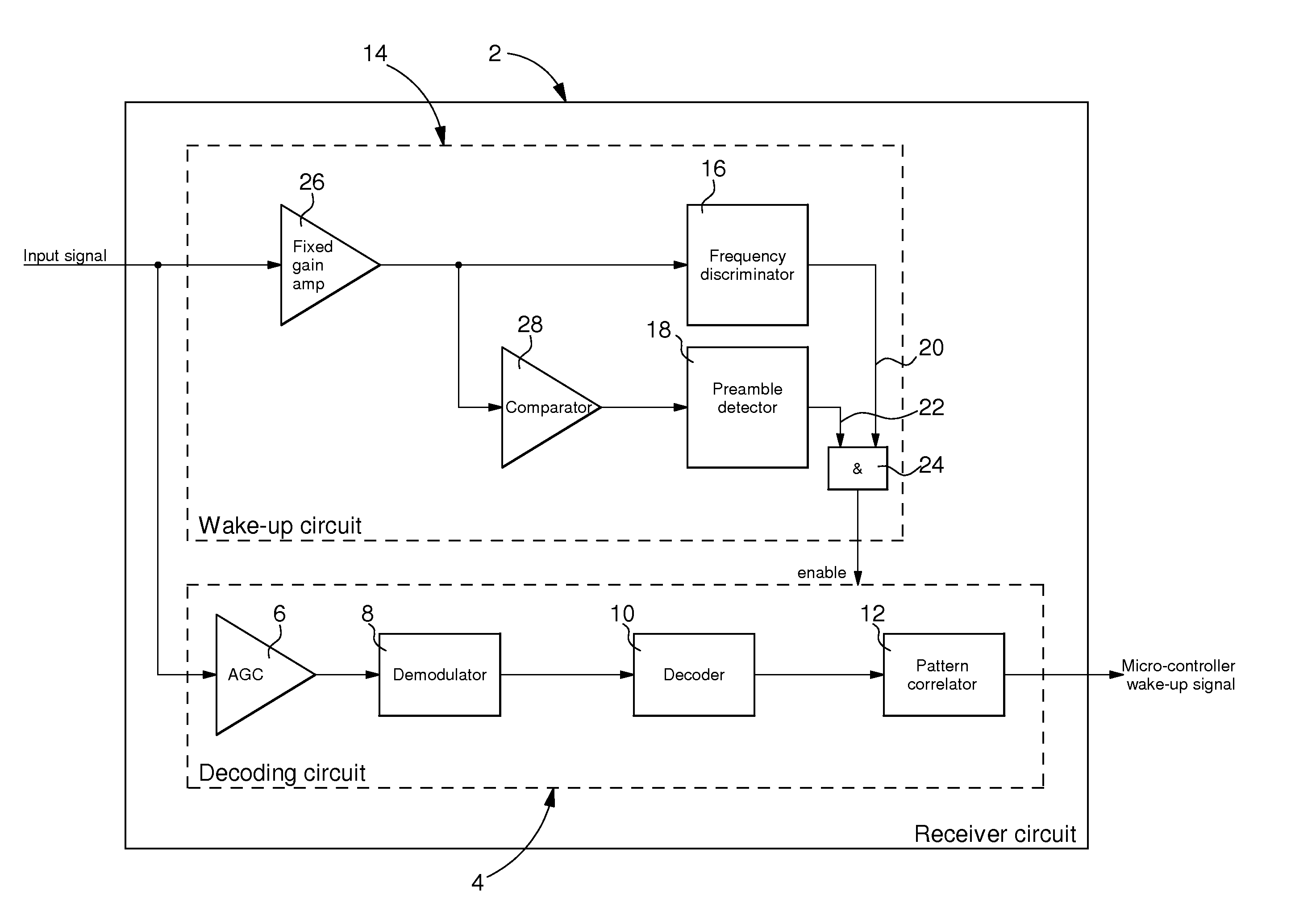
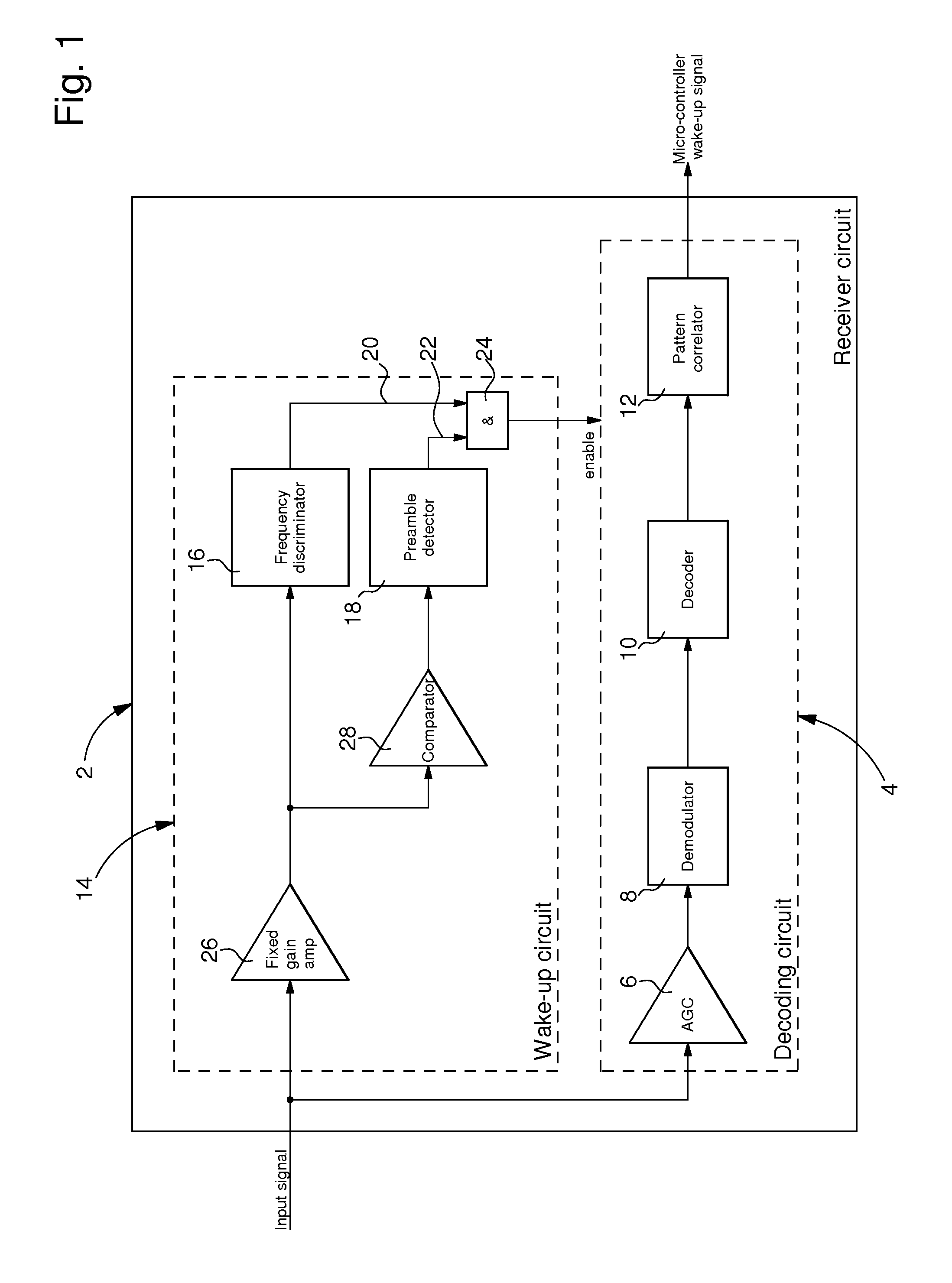
[0041]With the help of FIG. 9, the invention will be described. The transponder comprises a receiver circuit 2 comprising an entry amplifier formed by an AGC amplifier 6, a decoding circuit 5 and a wake-up circuit 14A. The decoding circuit 5 comprises an active demodulator 8 formed by an active envelope detector 8A followed by an analog-to-digital converter 8B (ADC). Such an active demodulator is preferred because it has a high sensitivity. However, this active demodulator has a relatively high electrical consumption (more than 1 μA and possibly around 1.2 μA). The digital part 9 of the decoding circuit comprises a decoder 10 and a pattern correlator 12. It is to be noted that this digital part could be arranged in a logic circuit having further functions, i.e. be part of a logic unit. This logic part of the decoding circuit 5 has also a relatively high electrical consumption (e.g. around 1 μA). Thus, the decoding circuit 5 generally consumes more than two microamperes (>2 μA). Acco...

fourth embodiment

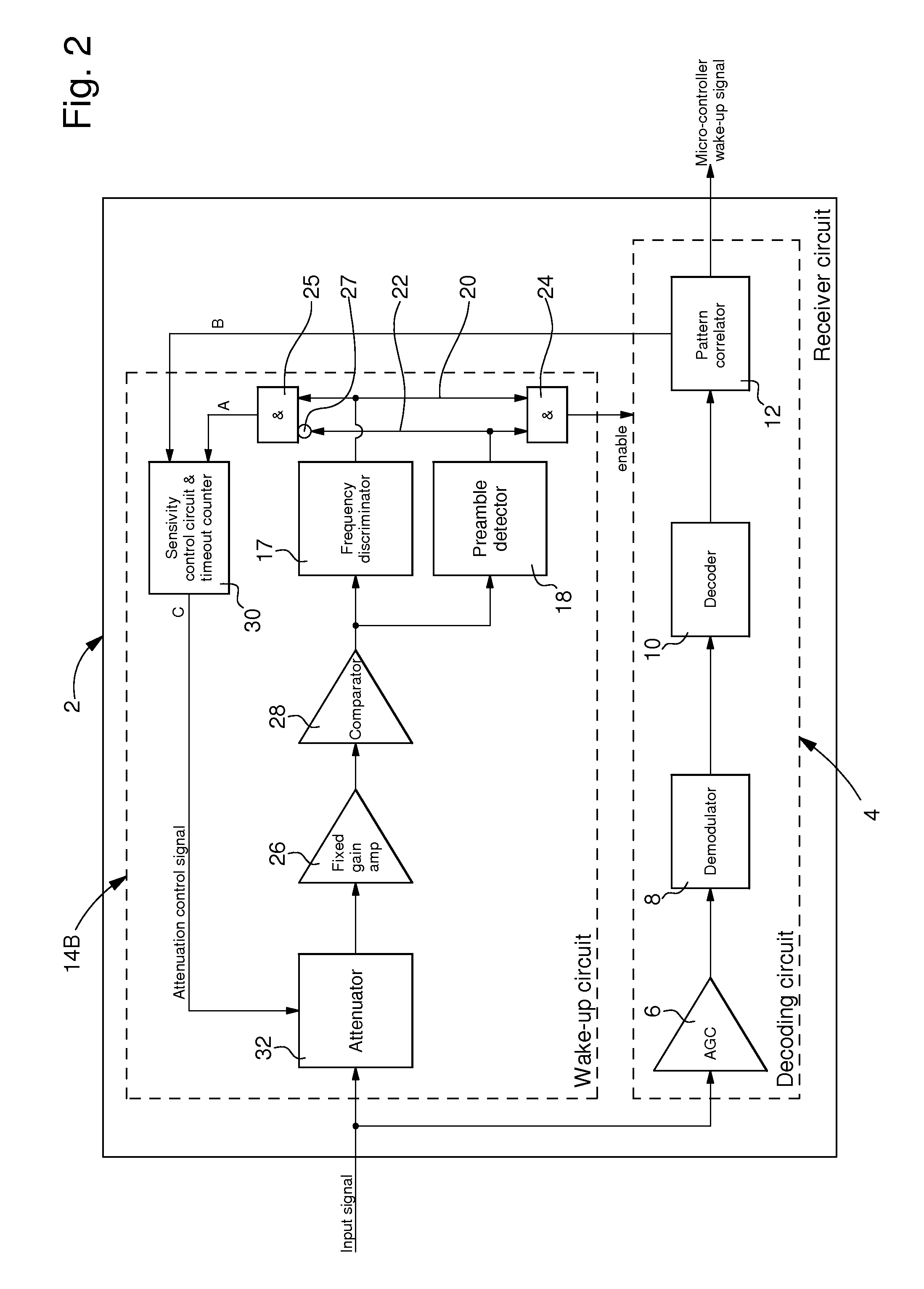
[0064]An improved fourth embodiment will now be described with the help of FIGS. 7 and 8. Already described elements will not be described again in detail hereafter. The transponder of FIG. 7 essentially differs from the one of FIG. 2 in that the sensitivity control unit is further implemented to reduce, if the sensitivity is greater than a minimum level, the sensitivity of the wake-up circuit 14C when the carrier frequency of a received RF signal is above the valid frequency range (Frequency ok) or in a second frequency range higher than this valid frequency range. To that end, the frequency discriminator 56 is arranged for distinguish between a first frequency of the carrier of a RF signal within a first frequency range corresponding to a valid or correct frequency (F=ok) and a second frequency which is above this first frequency range or within a second frequency range located above the first one. Further, an ‘OR’ logic element (OR gate) 60 is implemented in the sensitivity contr...


PUM


Abstract

The transponder comprises an antenna and a receiver circuit (2) for receiving RF signals, this receiver circuit is implemented with a control mechanism to activate it at least periodically in a listening mode. This receiver circuit is comprises a decoding circuit (4), formed at least by a demodulator (8) and a decoder (10), and a wake-up circuit (14B) to analyze received RF signals in the listening mode and arranged for controlling the activation of the decoding circuit in this listening mode. The wake-up circuit comprises a frequency discriminator (17) and a digital modulation or preamble detector (18) downstream from a field clock generator (28). The wake-up circuit receives as entry an alternating signal branched from the signal chain through the receiver circuit upstream from the demodulator and it activates the decoding circuit only when a modulation or a preamble is detected in a received RF signal by the digital modulation or preamble detector.

Description

FIELD OF THE INVENTION[0001]The present invention concerns the domain of transponders comprising of an antenna and a receiver circuit for receiving RF signals which are amplitude modulated (AM). The receiver circuit generally comprises a demodulator, a decoder and often a wake-up circuit controlling the activation of at least a part of the receiver circuit and / or of a main logical unit in a transponder's listening mode or standby mode. The present invention is valid for any number of channels a device is supporting (typically 1 or 3 channels). More particularly, the present invention concerns transponders having an internal supply source like a battery, e.g. active transponders.BACKGROUND OF THE INVENTION[0002]To optimize current consumption in the receiver of a transponder equipped with a battery, a typical case is to use polling method. In such a polling method, the receiver is active (ON state) for a certain ON time period (or polling-on period) followed by an OFF time period (or...

Claims


Application Information

Patent Timeline
Patent Type & Authority Applications(United States)
IPC IPC(8): H04B1/16
CPCH04B1/1615G06K19/0726H04W52/0238H04W52/0229H04W52/028Y02D30/70
Inventor PRAZAN, MICHALPROKES, MICHALFEHLE, JURGEN
Owner SMARTRAC TECH WEHNRATH
Why Eureka
Try Eureka