
Medicament Delivery Device

a technology of delivery device and medicament, which is applied in the direction of medical devices, intravenous devices, medical devices, etc., can solve the problem of not achieving optimal reduction of overall size, and achieve the effect of reducing the number of components and reducing the overall size of the devi

Active Publication Date: 2013-04-18
SHL MEDICAL AG
View PDF7 Cites 19 Cited by
  • Summary
  • Abstract
  • Description
  • Claims
  • Application Information

AI Technical Summary

Benefits of technology

The present invention is about a medicament delivery device that is small and easy to use with fewer components. It uses a rotating hub and a spring to provide motion. The device also has grooves and a protrusion to control the dose quantity and allows for multiple doses to be stored from the same medicament container. Overall, it has a compact design and is cost-effective to manufacture.

Problems solved by technology

However, the non-linear compartment for said negator spring comprises a first axel member establishing a rotating axis for a centrally disposed circular-shaped spindle having a peripheral surface for supporting movement therealong of plural interconnected spheres serving as a piston rod, and a second axel member establishing a rotating axis for a centrally disposed spool which supports the helical coils of the negator spring; thus also resulting in no optimal reduction of the overall size.

Method used


Image

  • Medicament Delivery Device
  • Medicament Delivery Device
  • Medicament Delivery Device

Examples


first embodiment

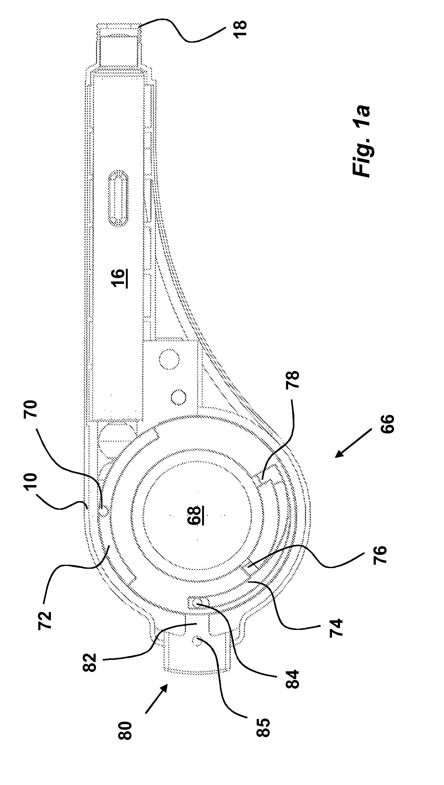
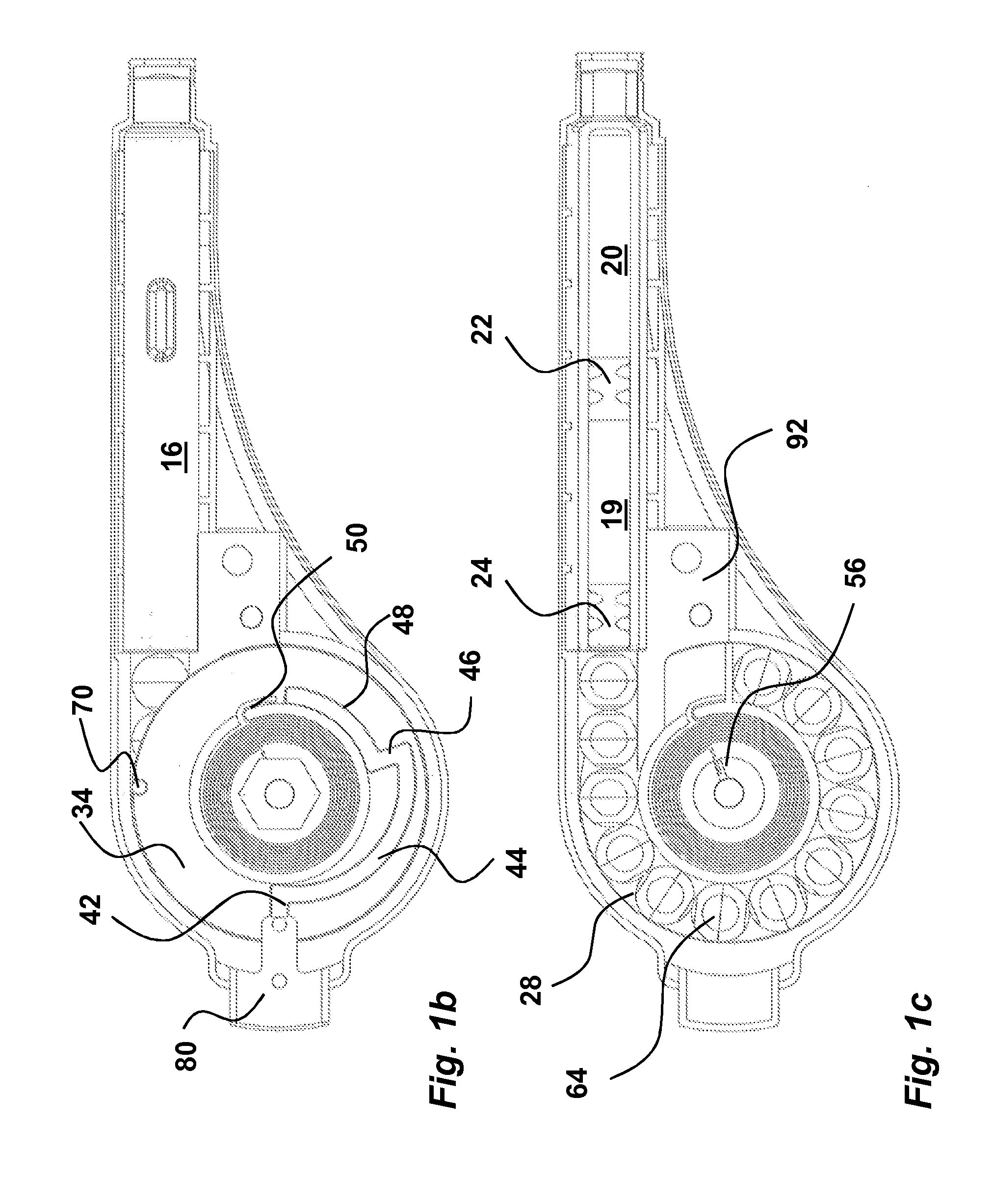
[0039]In the first embodiment, as seen in FIG. 1b, the first groove is arranged with at least two first radially 42, 46 and at least two first generally circumferentially 44, 48 directed groove sections respectively, in succession, wherein the first of said first generally circumferentially directed groove sections 44 is arranged with an increasing radius for forcing said activation member 80 towards the distal direction from its depressed position to its non-depressed position, and wherein the last of said first generally circumferentially directed groove sections 48 is arranged with a constant radius, whereby said activation member is held in the depressed position, indicating that the device is used.

second embodiment

[0040]In the second embodiment, as seen in FIG. 11b, the first groove is arranged with a plurality of first radially 42′, 46′, 47 and first generally circumferentially 44′, 45, 48′ directed groove sections in succession providing the delivery of a plurality of doses of medicament, wherein the firsts of said first generally circumferentially directed groove sections 44′, 45 are arranged with an increasing radius for forcing said activation member 80 towards the distal direction from its depressed position to its non-depressed position, and wherein the last of said first generally circumferentially directed groove sections 48′ is arranged with a constant radius, whereby said activation member is held in the depressed position, indicating that the device is used.

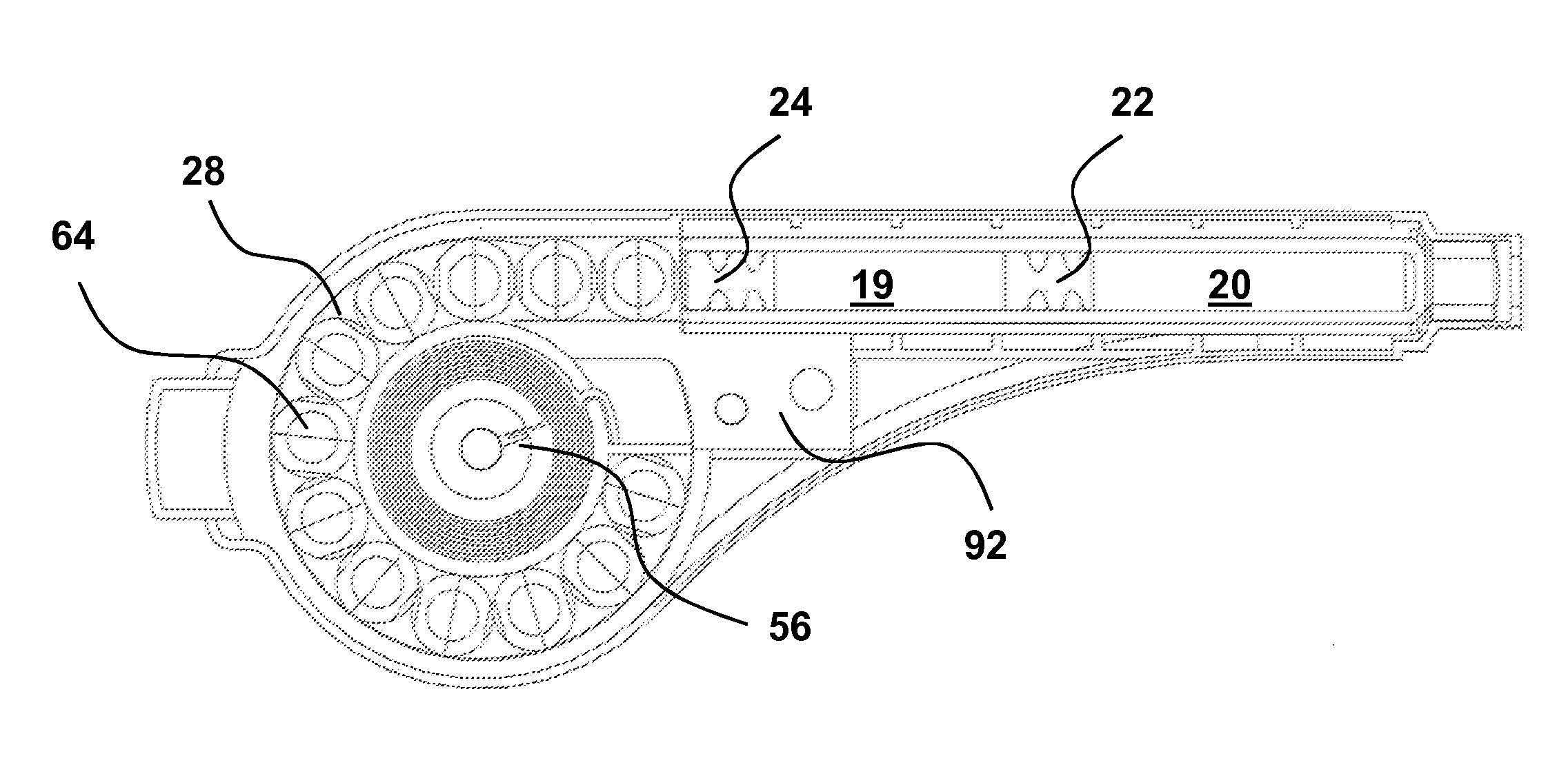
[0041]In the first embodiment the medicament container 16 is of a so called dual chamber type, FIG. 1c, wherein said medicament container comprises two compartments 19, 20, each compartment containing a substance and being sepa...


PUM


Abstract

A medicament delivery device includes a housing with a circle-segment-shaped compartment for a drive unit that moves at least one stopper in a medicament container and that includes a support wheel and central hub on which first and second parallel disks are fixedly attached and interconnected by an abutment cross-wall; spherical members between the abutment wall and adjacent the stopper; a clock spring within the hub with an outer end connected to the hub and an inner end connected to a one-direction-rotatable tubular hub coaxially arranged around a shaft fixedly attached to a housing part; and an activation member connected to the first disk by a hold-and-release mechanism. When the activation member is not depressed, the wheel and spring are held in a tensioned static state, and when the activation member is depressed, the spring and wheel are released and the spherical members are forced against the stopper.

Description

TECHNICAL AREA[0001]The present invention relates to a medicament delivery device and in particular a medicament delivery device that is compact and simple to handle.TECHNICAL BACKGROUND[0002]There are numerous medicament delivery devices that have been invented and developed during the years. These devices have been provided with different degrees of functionality and automatic features, such as mixing of medicament components, priming, dose delivery, penetration, just to mention a few.[0003]Many devices are arranged with an elongated plunger rod that acts on stoppers inside a medicament container. The plunger rod is pushed in the distal direction by drive force members that often are spiral compression springs. This configuration means that the device becomes quite long since the spring acts on a distal end of the plunger rod, a so called pen injector.[0004]In many instances the users do not want these elongated pen-type injectors due to their form, and a few attempts have been ma...

Claims


Application Information

Patent Timeline
IPC IPC(8): A61M5/315
CPCA61M5/2033A61M5/2066A61M5/2448A61M5/3129A61M5/31596A61M5/31593A61M2005/2073A61M2005/31518A61M5/31566A61M5/31511A61M5/1454A61M5/14566A61M5/14244
Inventor HOLMQVIST, ANDERSGUSTAFSSON, MAGNUSLOOF, STEFANRATJEN, JOCHEN
Owner SHL MEDICAL AG
Learn More