Solar water heating system with double-row vacuum tubes

Inactive Publication Date: 2013-04-25
LEI SHUNAN
View PDF7 Cites 3 Cited by
  • Summary
  • Abstract
  • Description
  • Claims
  • Application Information

AI Technical Summary

Benefits of technology

The patent aims to solve the issue of limited lighting surfaces without adding to the size of the equipment. The invention provides a solution to make the effective lighting surfaces larger without changing the overall size of the device.

Problems solved by technology

The thermal efficiency of this type of implementation is limited due to the small lighting surface.

Method used


Image

  • Solar water heating system with double-row vacuum tubes
  • Solar water heating system with double-row vacuum tubes
  • Solar water heating system with double-row vacuum tubes

Examples


Embodiment Construction

[0017]While the present invention may be embodied in many different shapes, forms, designs or configurations, for the purpose of promoting an understanding of the principles of the invention, reference will be made to the embodiments illustrated in the drawings and specific language will be used to describe the same. It will nevertheless be understood that no limitation of the scope of the invention is thereby intended. Any alterations and further implementations of the principle, the essence or the spirit of the invention as described herein are contemplated as would normally occur to one skilled in the art to which the invention relates.

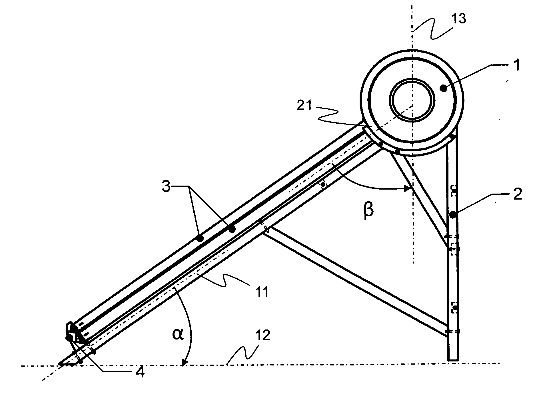
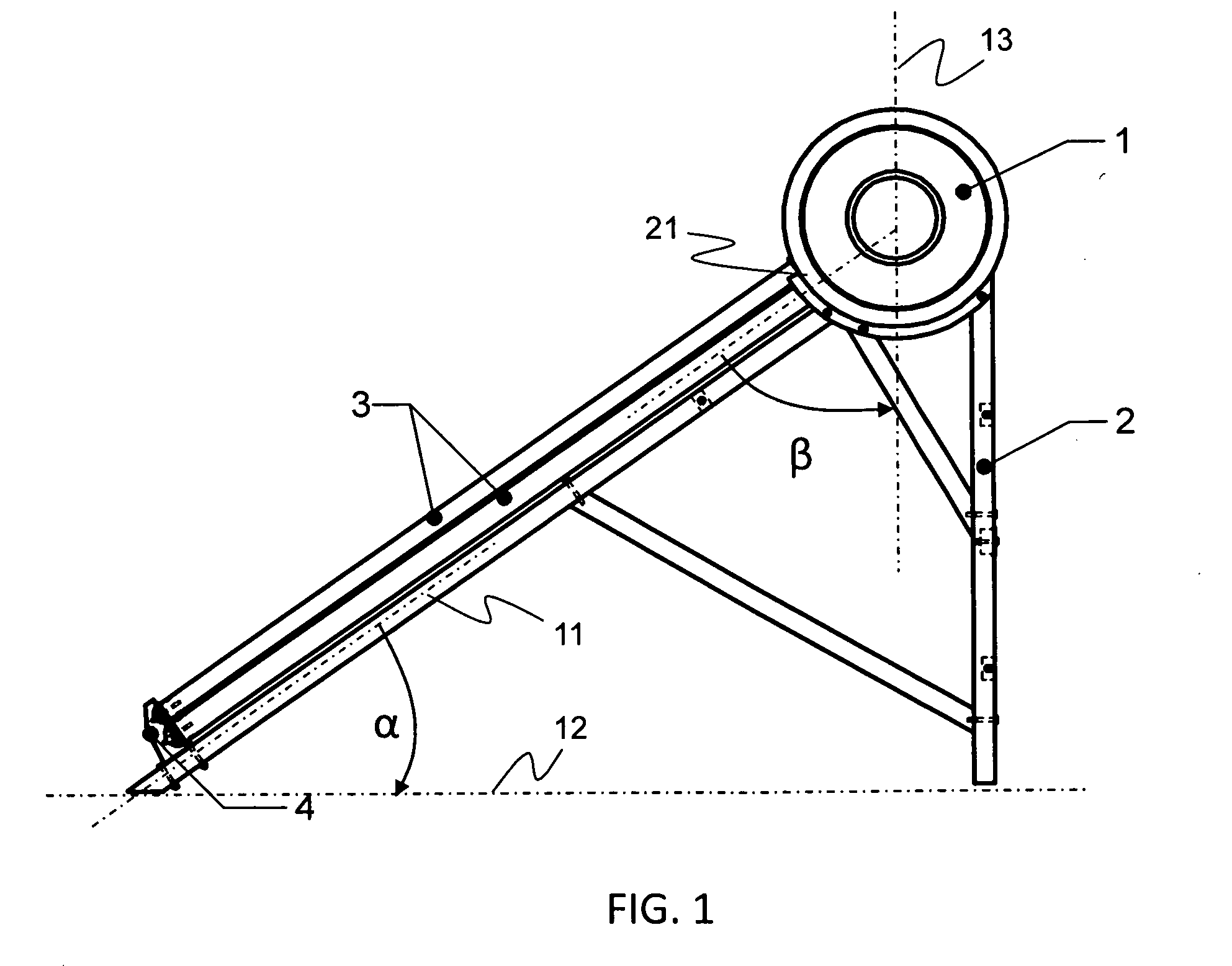
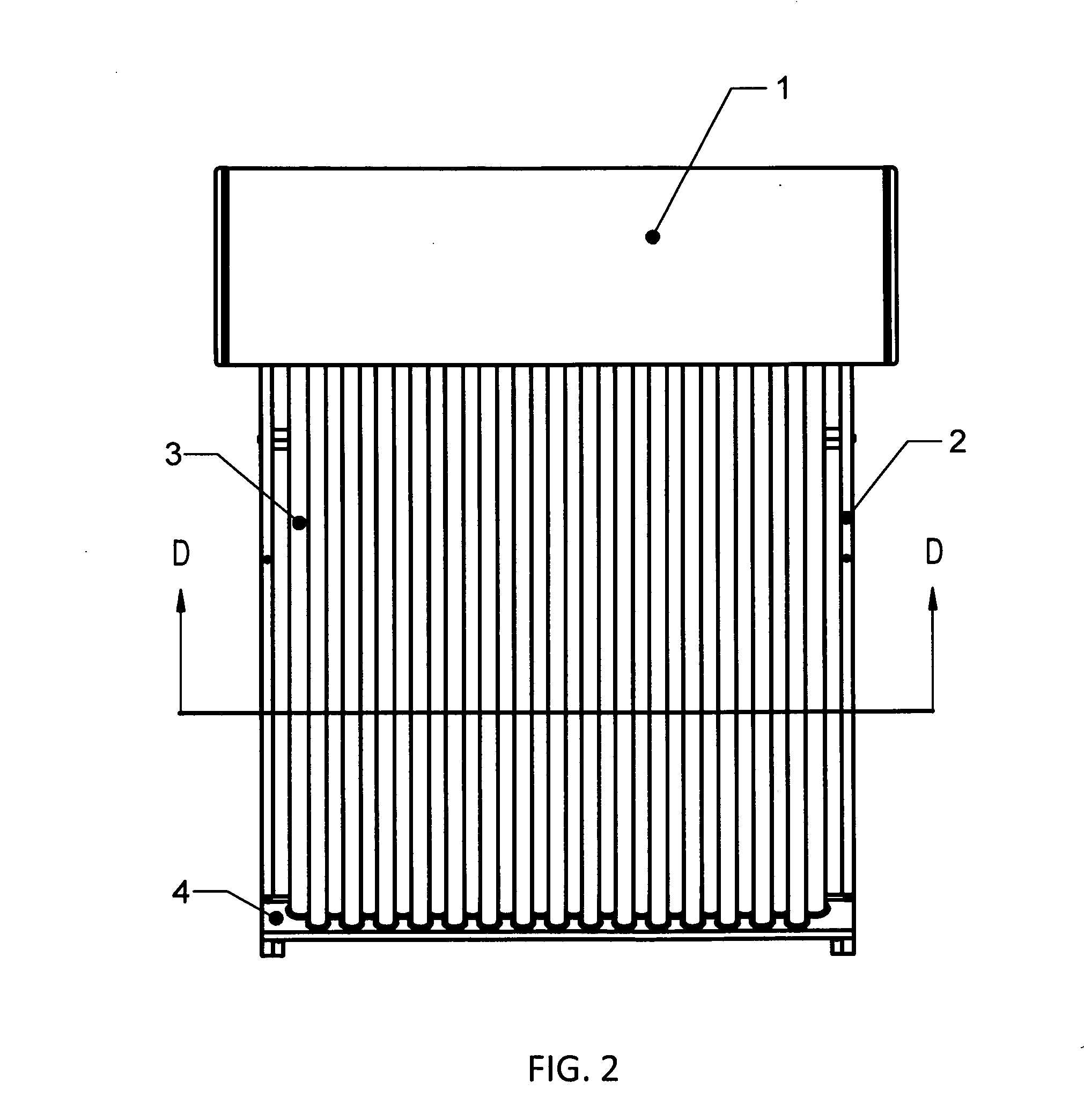
[0018]FIG. 1 illustrates a side view of the solar heating system according to the present invention. FIG. 2 illustrates a top view of the heating system according to FIG. 1.

[0019]The heating system according to FIG. 1 and FIG. 2 includes a thermos 1, a frame 2, a two-layer array of vacuum tubes 3, and a supportive accessory 4 to support the lower e...


PUM


Abstract

The invention provides a solar water heating apparatus with double-row vacuum tubes coupled to a water tank made of stainless steel or enamel. Each of the vacuum tubes is made of an exterior tube and an interior tube separated by a vacuum. The exterior tube is transparent. The interior tube is covered with a layer of light-absorption material. When sunlight shines on the vacuum tube, the water in the tank and the water in the interior tube circulate by convection.

Description

FIELD OF THE INVENTION[0001]This invention generally relates to the technology of using solar thermal energy. In particular, this invention relates to a solar water heating system with double-row vacuum tubes coupled to a water tank made of stainless steel or enamel.BACKGROUND OF THE INVENTION[0002]Solar water heaters have been widely used for years in many countries. Most of solar water heaters in the market use vacuum tubes for collecting heat energy from sun lights. The vacuum tubes are arranged in an array of a single row and multiple columns. The thermal efficiency of this type of implementation is limited due to the small lighting surface.[0003]What is desired is a solution to enlarge the effective lighting surfaces without changing the overall length and width of the apparatus.SUMMARY OF THE INVENTION[0004]The present invention provides a solution to enlarge the effective lighting surfaces without changing the overall length and width of the equipment.[0005]The apparatus acco...

Claims


Application Information

Patent Timeline
IPC IPC(8): F24J2/00
CPCF24J2/055Y02E10/44F24J2/345F24S10/45F24S60/30
Inventor LEI, SHUNAN
Owner LEI SHUNAN
Why Eureka
Try Eureka