
Residual radioactive sludge liquid suction apparatus

a liquid suction device and radioactive sludge technology, applied in the direction of machines/engines, nuclear engineering, transportation and packaging, etc., can solve the problem of transferring sludge on its own, and achieve the effect of maximally reducing the radiation exposure of an operator

Active Publication Date: 2013-04-25
TAIHEI DENGYO KAISHA
View PDF15 Cites 5 Cited by
  • Summary
  • Abstract
  • Description
  • Claims
  • Application Information

AI Technical Summary

Benefits of technology

The patent describes a transfer device for sludge that can be controlled by remote using monitoring cameras. The device reduces the exposure of operators to radiation. It can crush the sludge finely using highly pressurized water jet and blasting air. The device uses the supernatant solution initially stored in the sludge tank for crushing, which reduces the amount of radioactive disposal. The conventional transfer device has the advantage of transferring all the sludge from the tank to another tank, but it also has the disadvantage of leaving a small amount of sludge liquid in the tank, which may be transferred manually and expose the operator to radiation.

Problems solved by technology

Further, the supernatant solution is generated by a reason such that when the sludge is transferred to the storage tank, it is impossible to transfer the sludge on its own, so that it is necessary to transfer the sludge as sludge liquid having fluidity by being mixed with water or like.

Method used


Image

  • Residual radioactive sludge liquid suction apparatus
  • Residual radioactive sludge liquid suction apparatus
  • Residual radioactive sludge liquid suction apparatus

Examples


Embodiment Construction

[0051]One embodiment (mode) of a residual radioactive sludge suction apparatus according to the present invention will be described hereunder with reference to the accompanying drawings.

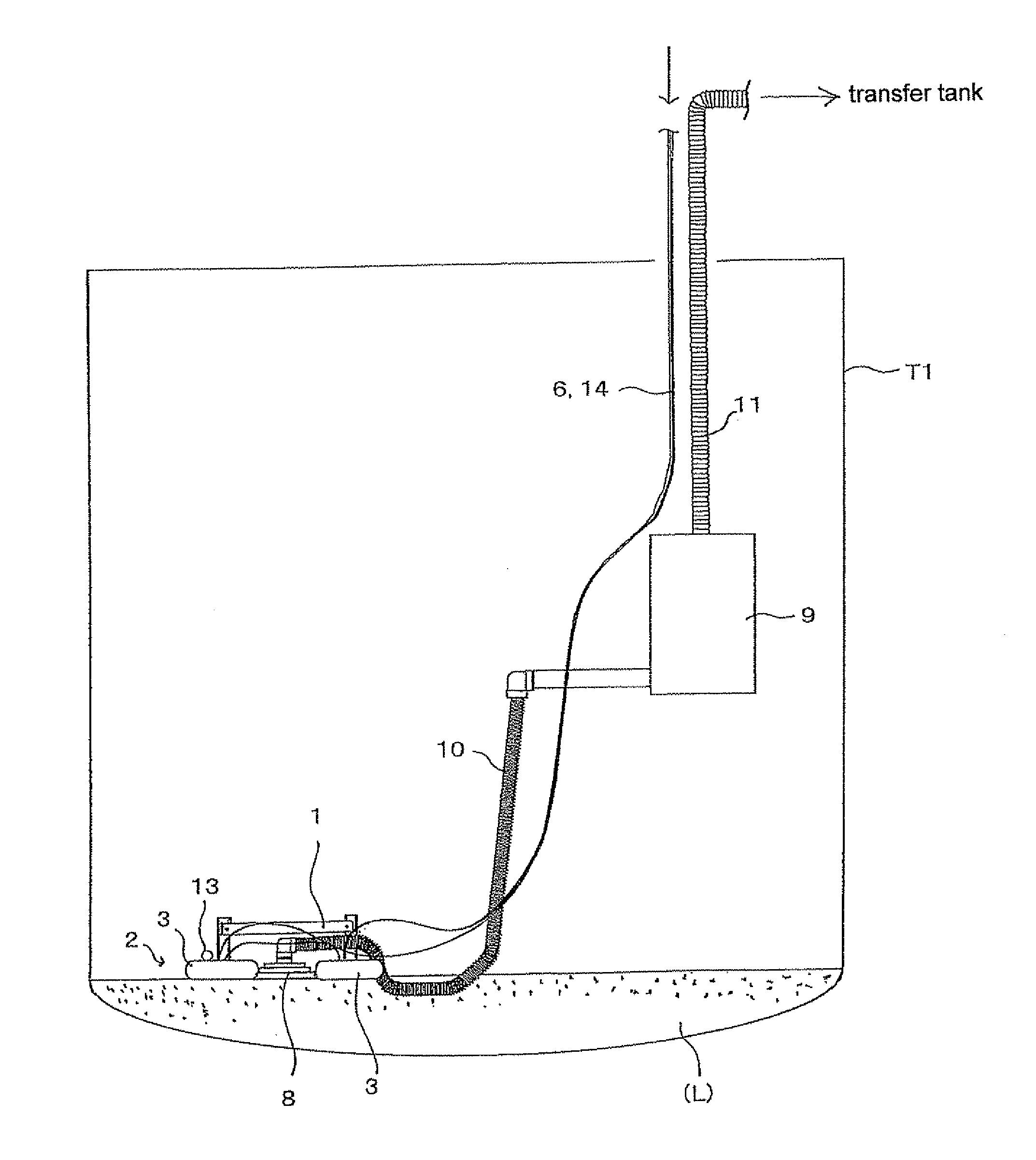
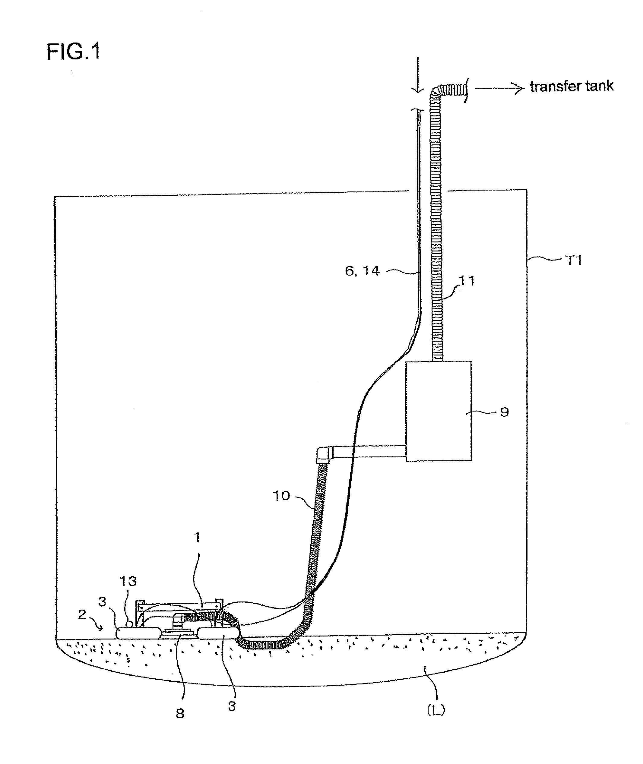
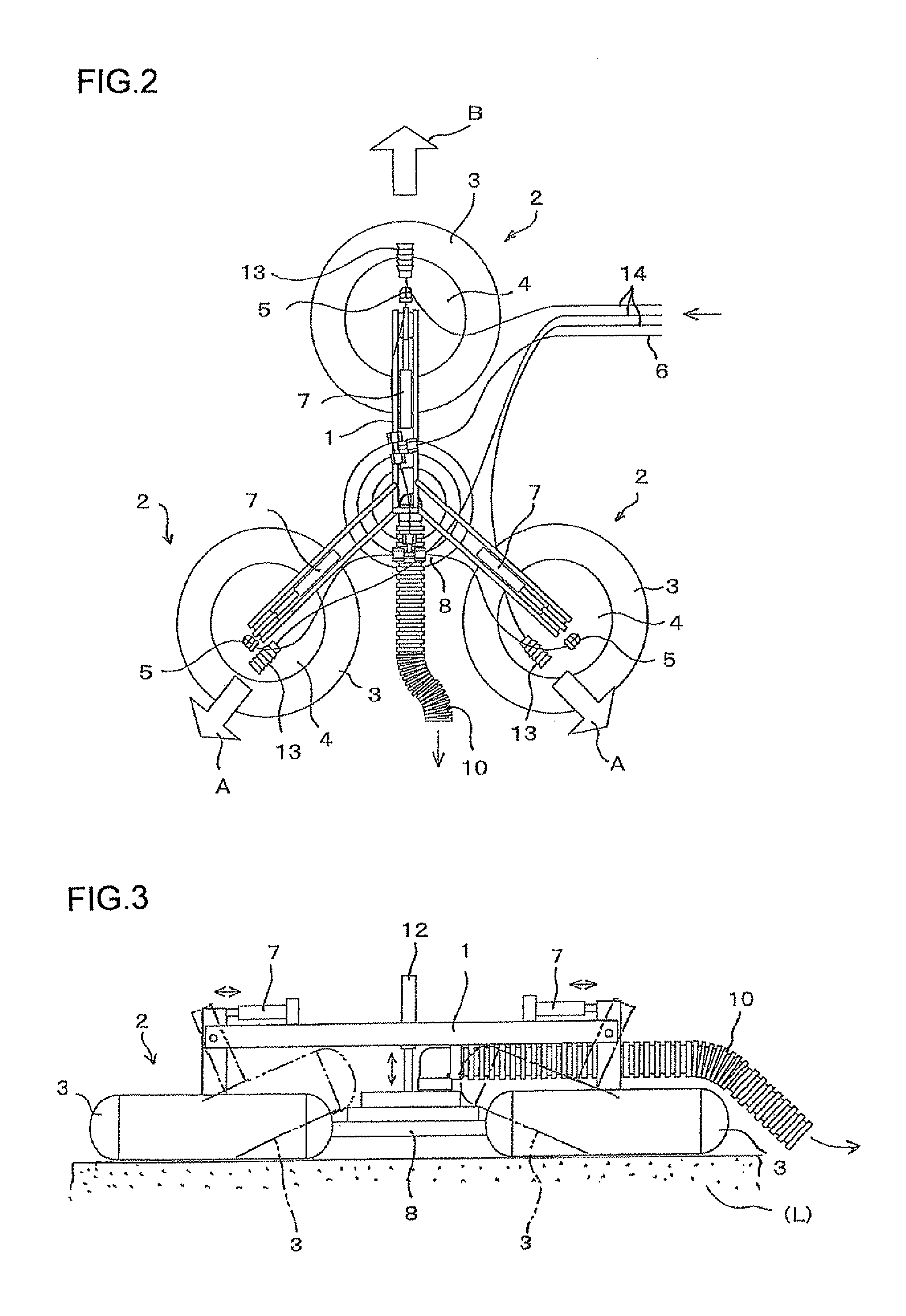
[0052]FIG. 1 is an illustration for explaining sludge liquid sucking operation by using a residual radioactive sludge liquid suction apparatus according to the present invention, FIG. 2 is an illustrated plan view showing the residual radioactive sludge suction apparatus according to the present invention, FIG. 3 illustrates a front view of the residual radioactive sludge suction apparatus according to the present invention, and FIG. 4 is a view explaining function of a hover skirt (hovercraft skirt) of the residual radioactive sludge suction apparatus according to the present invention.

[0053]With reference to FIGS. 1 to 4, reference character T1 denotes a sludge storage tank as one tank. In the sludge storage tank T1, there remains a small amount of sludge liquid after the transfer of the sludge fro...


PUM


Abstract

There is provided a residual radioactive sludge liquid suction apparatus capable of safely and surely sucking radioactive sludge liquid remaining in a sludge storage tank with no fear of being exposed to radiation at a time when a small amount of sludge liquid remaining in the sludge storage tank is transferred to another tank. The suction apparatus is a residual radioactive sludge liquid suction apparatus used for sucking residual radioactive sludge liquid (L) at a time when the residual sludge liquid (L) remaining in a sludge storage tank T1 is transferred, and includes: a suction apparatus body 1; three hover skirts 2 mounted to the suction apparatus body 1; a suction head 8 mounted to the suction apparatus body 1 and configured to suck the residual sludge liquid (L); air jetting nozzles 13 mounted to the hover skirts 2, respectively; and an air supply source that supplies air to the hover skirts and the air jetting nozzles, wherein the suction apparatus body 1 floats on a surface of the residual sludge liquid (L) by supplying the air from the air supply source to the hover skirts, and moves on the surface of the residual sludge liquid (L) by jetting the air from the air supply source through the air jetting nozzles 13.

Description

FIELD OF THE INVENTION[0001]The present invention relates to a residual radioactive sludge liquid suction apparatus, and more particularly, to a residual radioactive sludge liquid suction apparatus capable of safely and surely sucking radioactive sludge liquid (liquid sludge) in a sludge storage tank with no fear of being exposed to radiation at a time of transferring a small amount of sludge liquid contaminated by radioactive substance remaining in the sludge storage tank to another tank.BACKGROUND TECHNOLOGY[0002]A radioactive sludge contaminated by radioactive substance (called merely “sludge” hereinafter) composed of an ion exchange resin or filtration auxiliary agent and the like, which may be generated according to the operation (i.e., running) of a nuclear power plant, is stored for a certain predetermined time in a sludge storage tank together with supernatant solution for attenuating radiation, thereafter, taken out from the sludge storage tank, and then, transferred to and...

Claims


Application Information

Patent Timeline
IPC IPC(8): F17D1/14
CPCG21F9/04F17D1/14G21F9/22Y10T137/86083
Inventor AIZAWA, MASAHIROOGATA, OSAMU
Owner TAIHEI DENGYO KAISHA
Learn More