Brake device

a technology of brake shoe and braking member, which is applied in the direction of brake system, brake arrangement with braking member, transportation and packaging, etc., can solve the problem of inability to maintain a constant gap between the tread surface and the brake shoe, and achieve the effect of easily changing the distance between the operation member and the control surface and reliably adjusting

Active Publication Date: 2013-04-25
MITSUBISHI HEAVY IND ENG LTD
View PDF3 Cites 12 Cited by
  • Summary
  • Abstract
  • Description
  • Claims
  • Application Information

AI Technical Summary

Benefits of technology

[0030]According to the brake device described above, the distance of the operation member to the control surface can be changed easily, allowing the timing of gap adjustment to be adjusted.
[0031]According to the brake device described above, the operation member moves along the braking direction, and the position adjustment member changes the initial position o

Problems solved by technology

However, when repeated adjustments occurring as wear of the tread surface (braking target) progresses, cause the initial stroke position of the push rod 128 to move towards the braking side X1 in the braking direction, a problem occurs in that the movement of the adjustment push rod 147 relative to the distance moved (stroke) by the push rod 128 and the gap

Method used


Image

  • Brake device
  • Brake device
  • Brake device

Examples


Embodiment Construction

[0046]Embodiments of the present invention are described in detail below with reference to the drawings.

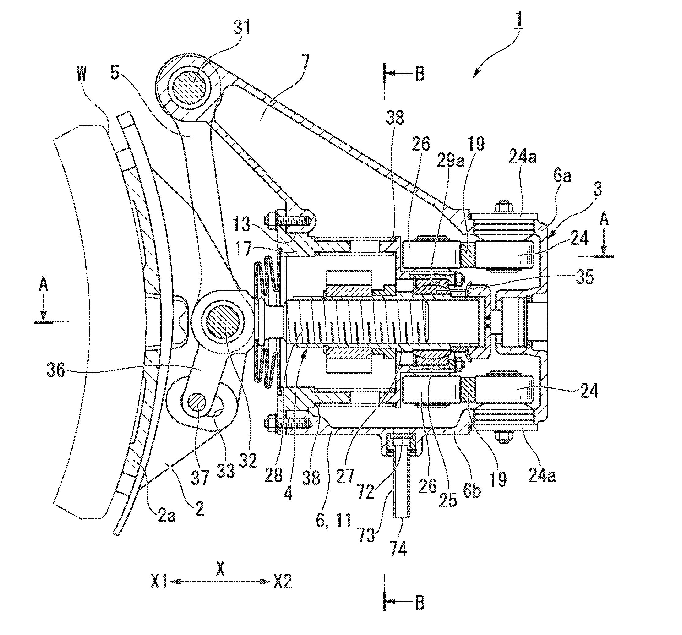
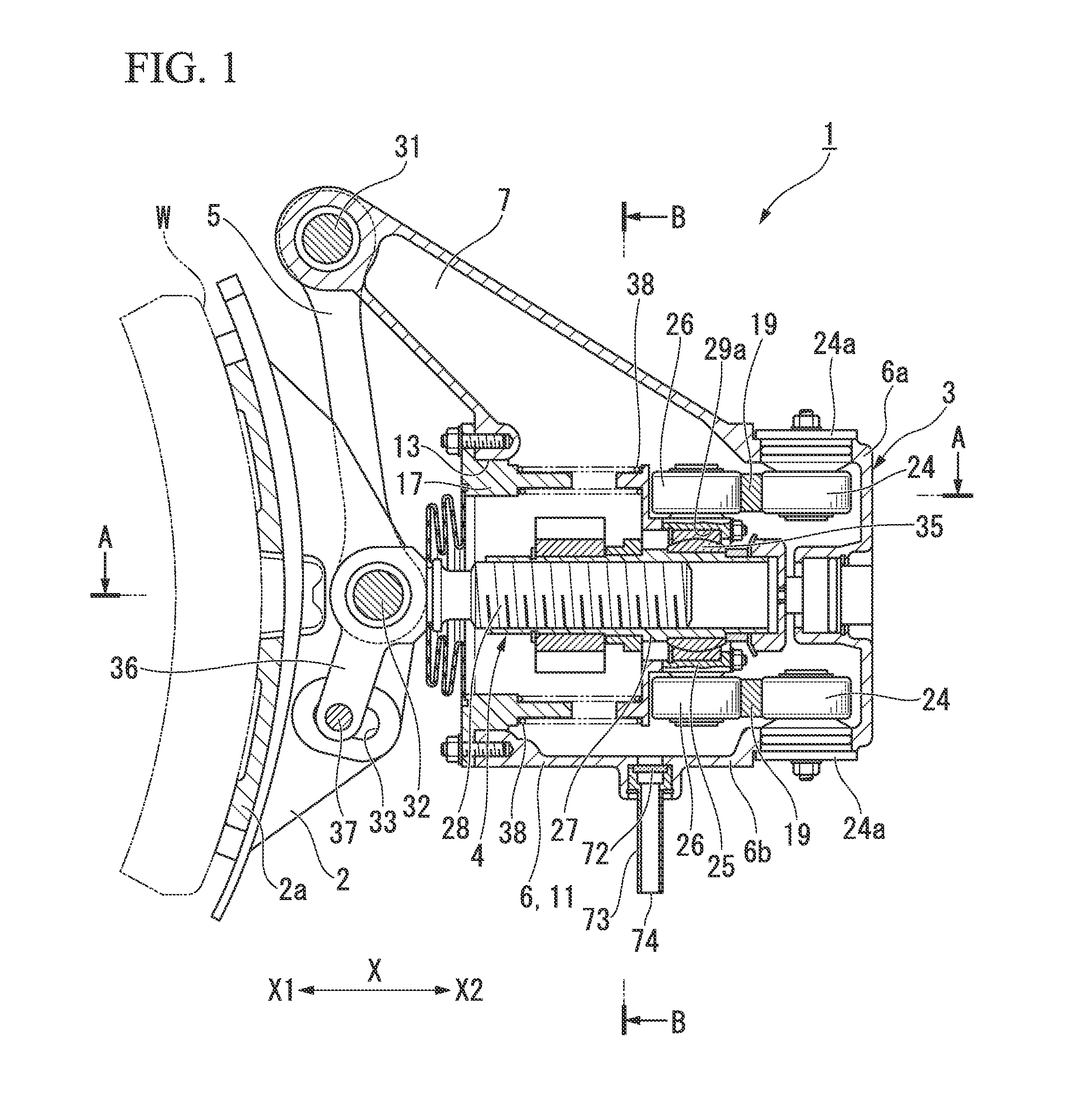
[0047]As shown in FIG. 1, a brake device 1 of the present embodiment is a brake device for use with railway vehicles, more specifically a single-shoe tread brake unit which pushes a brake shoe (damper) 2 against a tread surface W of a wheel from one side. The brake device 1 is disposed obliquely upward of the wheel, and is mounted to the vehicle at a mounting section 23 (see FIG. 2A) via bolts or the like.

[0048]As shown in FIG. 1, the brake device 1 includes as its main components; a brake shoe 2, a main unit 3 including an advancing and retreating unit 4, and a hanger 5. The brake shoe 2 contacts the tread surface W of the wheel serving as the braking target, and applies a braking force to the wheel. The advancing and retreating unit 4 moves the brake shoe 2 in a direction towards or away from the wheel. The hanger 5 movably supports the brake shoe 2.

[0049]The brake shoe 2 is a m...


PUM


Abstract

A brake device includes: a damper; an advancing and retreating member; and a gap adjustment mechanism. The gap adjustment mechanism has: a control section having a control surface facing an opposite side to a braking direction; an operation member whose movement is controlled by contacting the control surface as the advancing and retreating member advances towards the braking side in the braking direction, thereby enabling relative movement with respect to the advancing and retreating member towards the opposite side to the braking direction; and a position adjustment section which, when the advancing and retreating member advances towards the braking side in the braking direction, and the operation member relatively moves with respect to the advancing and retreating member, changes an initial position of the advancing and retreating member according to the relative movement amount of the operation member.

Description

BACKGROUND OF THE INVENTION[0001]1. Field of the Invention[0002]The present invention relates to a brake device which applies a braking force to a braking target such as a wheel. Priority is claimed on Japanese Patent Application No. 2011-229523, filed Oct. 19, 2011, the contents of which is incorporated herein by reference.[0003]2. Description of Related Art[0004]As a brake device that applies a braking force to a wheel, there is known a configuration that generates a braking force by pushing a brake shoe (damper) against the tread surface of a turning wheel. In this type of brake device, to prevent cumulative wear on the tread surface from widening the gap between the brake shoe and the tread surface, there is typically a configuration which incorporates an automatic gap adjustment mechanism (for example, Japanese Unexamined Patent Application, First Publication No. S 59-192666).[0005]An automatic gap adjustment mechanism is one which, when widening of the gap increases the stroke...

Claims


Application Information

Patent Timeline
IPC IPC(8): F16D65/38B61H15/00F16D49/00B61H1/00B60T1/04
CPCB60T1/04B61H1/00B61H15/00F16D65/18F16D2125/66F16D49/00F16D65/14F16D65/56F16D2121/04F16D65/54
Inventor FURUTANI, HIDEKI
Owner MITSUBISHI HEAVY IND ENG LTD
Why Eureka
Try Eureka