Rotation sensor-equipped bearing

a technology of rotating sensor and bearing, which is applied in the direction of sliding contact bearings, mechanical equipment, instruments, etc., can solve the problems of assemblage that requires a substantial amount of labor and time, cannot be reused, and the bearing assembly or the sensor cannot be replaced independently, so as to achieve convenient disassembly or disassembly, the effect of convenient handling

Active Publication Date: 2013-04-25
NTN CORP
View PDF3 Cites 21 Cited by
  • Summary
  • Abstract
  • Description
  • Claims
  • Application Information

AI Technical Summary

Benefits of technology

[0017]In view of the foregoing, the present invention has for its primary object to provide a rotation sensor equipped bearing assembly which can be easily disassembled or dismantled so that only a faulty or broken-down component part of one of the bearing assembly and the sensor mounting substrate can therefore be replaced to permit the other component part thereof to be reused; can be detached from an electric wiring section to enable it to be easy to handle; and in which by a simplified replacement of one or some component parts, various change in resolving power of the rotation detection and change in class of rotation detection such as, for example, a function of a simple rotation detection, a function of detecting the direction of rotation and a function of detecting the point of origin can be accomplished.
[0018]Another important object of the present invention is to provide a rotation sensor equipped bearing assembly of the type referred to above, which is compact in an axial direction and is easy to assemble and in which the number of component parts that are to be altered can be reduced even if the shape of the shaft changes.

Problems solved by technology

The bearing assembly disclosed in the patent document 1 listed above has a problem in that, where the rotation sensor is mounted on the rolling bearing assembly, the encoder is fitted to the inner ring of the bearing assembly by means of a press fitting technique and, therefore, the encoder can not be reused, and also the bearing assembly or the sensor cannot be replaced independently.
Also, since an electric connection with the sensor is accomplished directly without being routed through any wiring connector, the assemblage requires a substantial amount of labor and time to complete it.
For this reason, there has been found a problem that by a distance equal to the thickness of the substrate, the axial length of the rotation sensor equipped bearing assembly as a whole tends to become large.
Also, fitting of the substrate to the sensor housing requires the use of an insert molding and, for this reason, the need is recognized to set the substrate in a mold during the molding, thus requiring a substantial amount of labor and time.
Also, since a stopper necessary to engage the encoder with the shaft is provided in a support member which is a component part of the encoder, the axial length of the rotation sensor equipped bearing assembly tends to be increased and, accordingly, the compactness of, for example, a copying machine that is to be incorporated will be adversely affected.
Also, according to the respective structures disclosed in the patent documents 3 to 5 listed above, in a business office equipment, since the bearing assembly and a rotary encoder are installed separately, a substantial amount of labor and time is required for the bearing assembly and the rotary encoder to be incorporated in the business office equipment.
In addition, where the rolling bearing assembly disclosed in any of the patent documents 6 and 7 listed above and the rotary encoder are integrated together, since the sensor is assembled in a sensor unit in a fashion the sensor cannot be removed from such sensor unit, the reuse of the sensor is impossible.
Since the electric connection with the sensor is accomplished directly without being routed through the wiring connector, assemblage requires a substantial amount of labor and time.
Yet, since in the case of the sensor unit utilizing a magnetic sensor, the encoder used therein must be of a type utilizing a magnet, it tends to become costly as compared with the sensor unit of a type utilizing an encoder made of, for example, a resinous material.

Method used


Image

  • Rotation sensor-equipped bearing
  • Rotation sensor-equipped bearing
  • Rotation sensor-equipped bearing

Examples


first embodiment

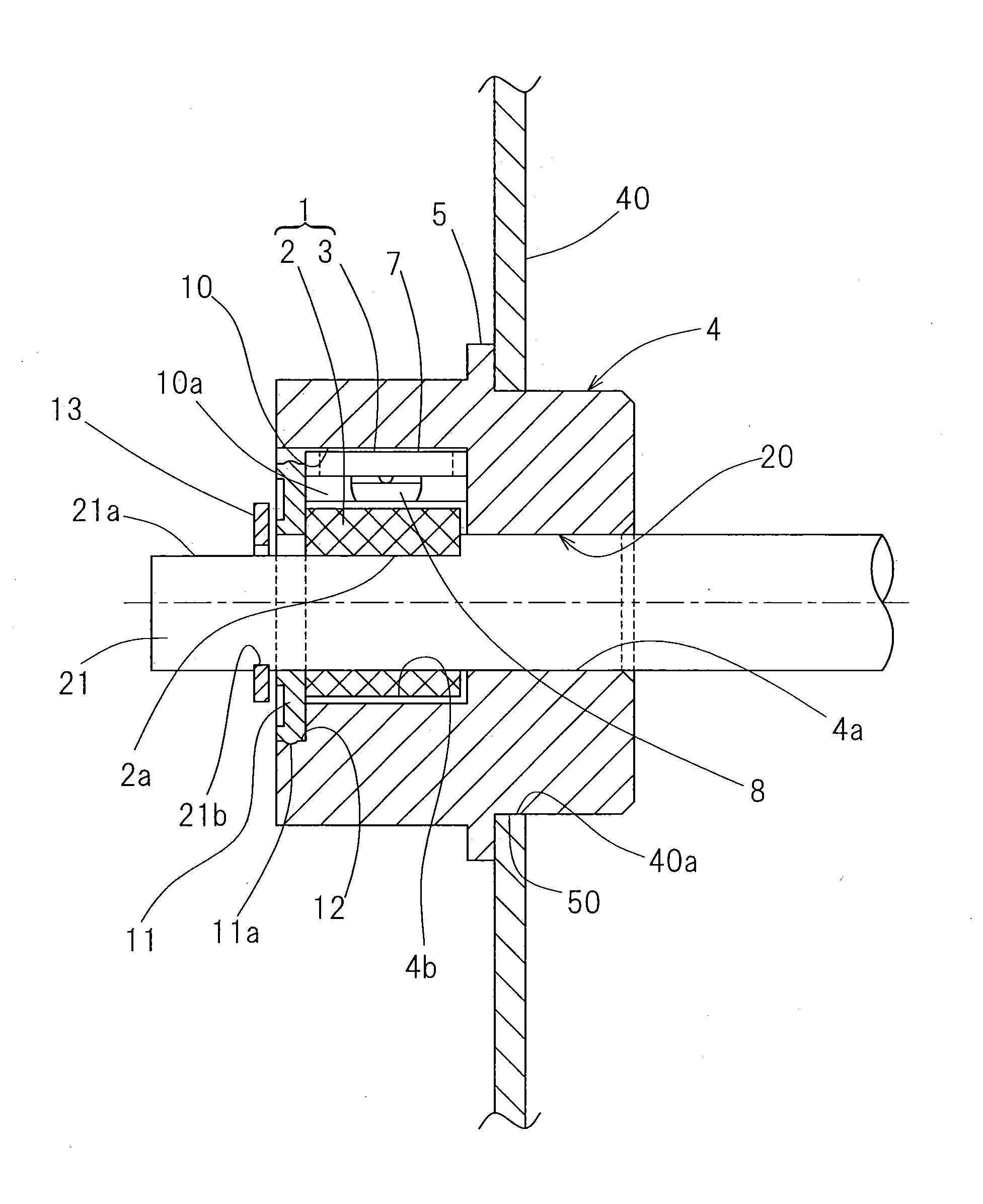
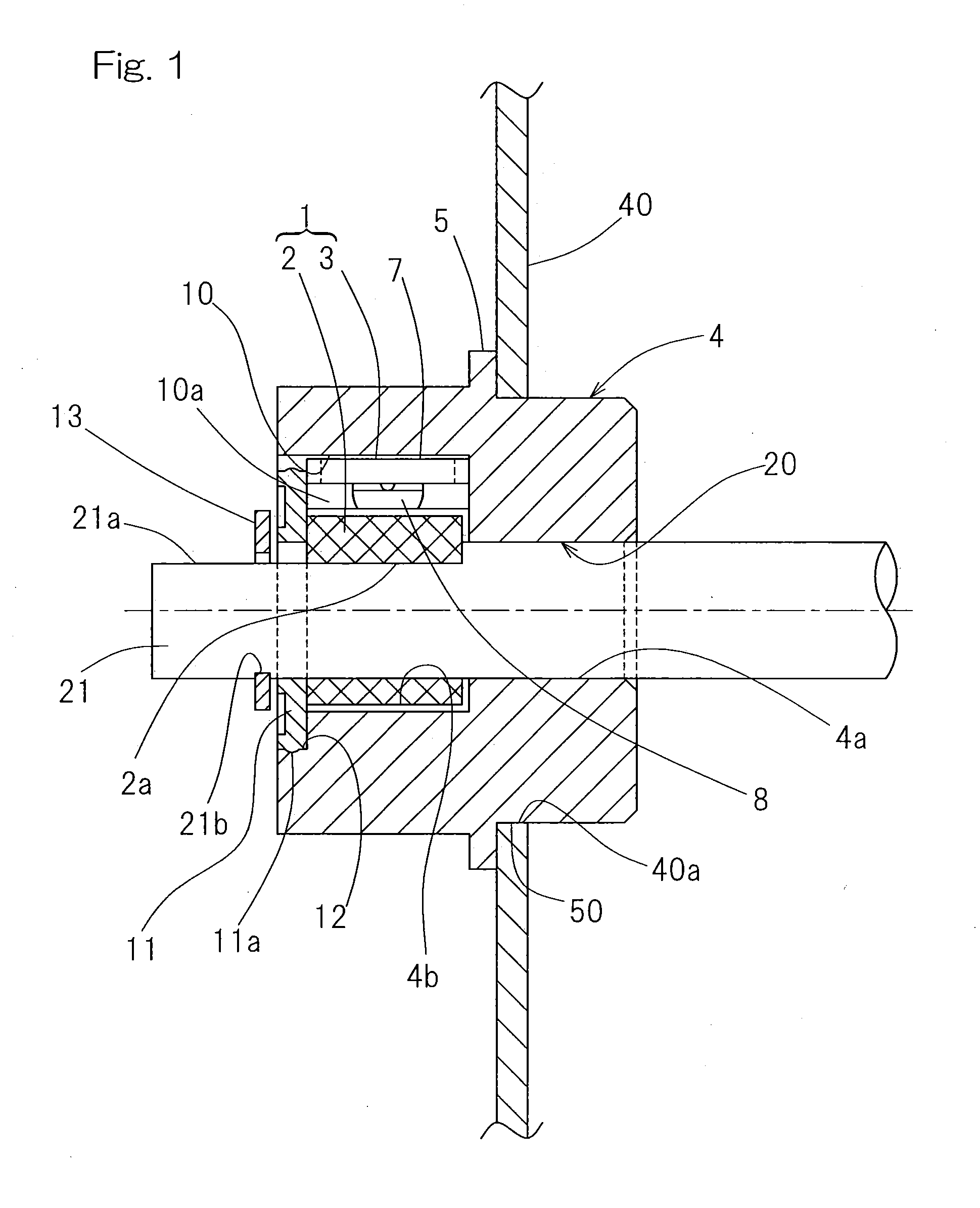
[0101]Also, since in the above described first embodiment, the use is made of the lid member 11 for enclosing the space delimited between the inner peripheral surface of the sensor housing 4 and the encoder 2 and is concurrently used as a detachment preventing member for avoiding detachment of the encoder 2 and the sensor unit 3 in the axial direction, the assemblage can be accomplishes further easily and the number of component parts can be reduced. Yet, since the lid member 11 and the encoder 2 are made insertable from the axial direction, the assemblage can be accomplished yet further easily.

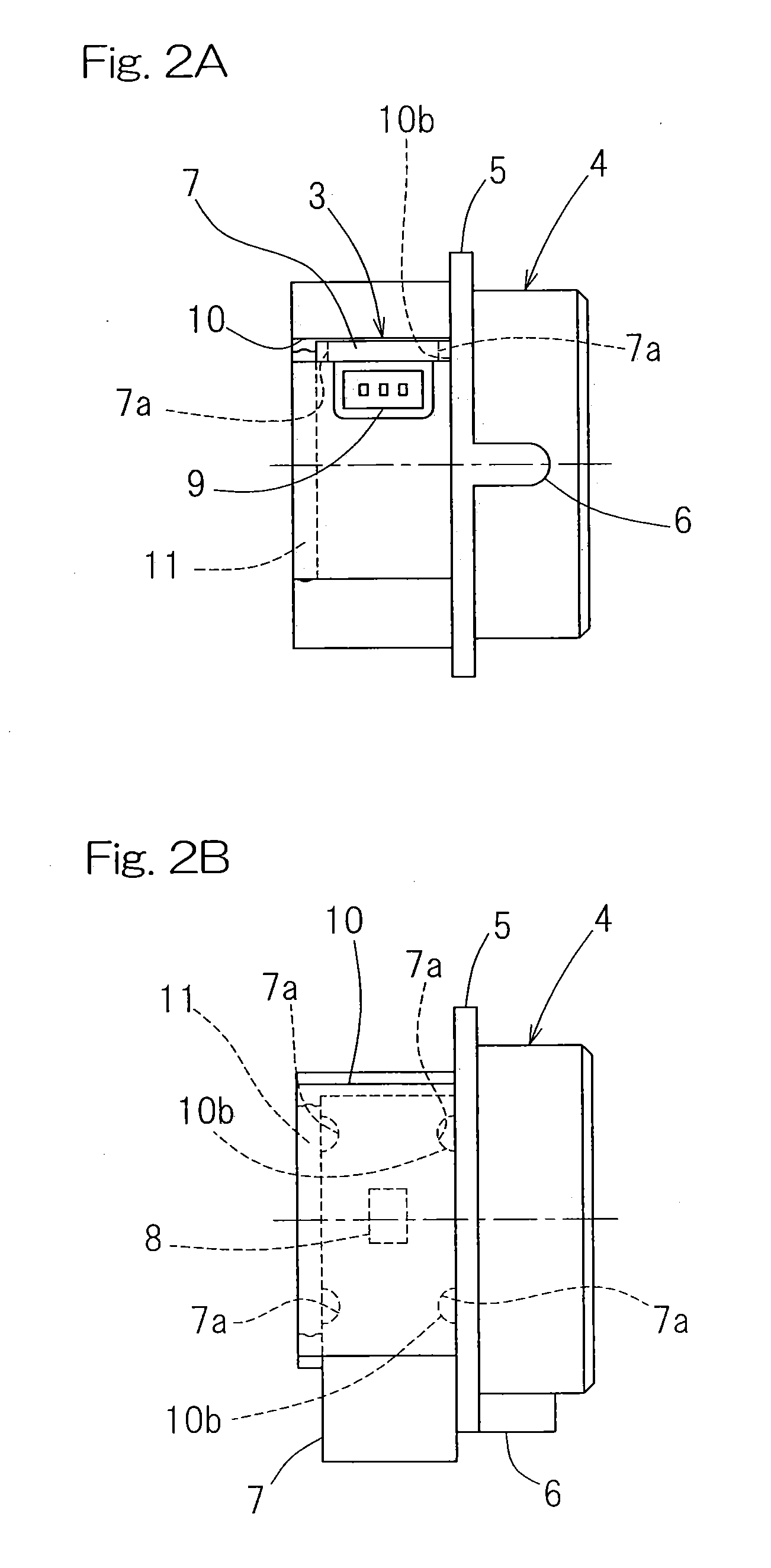
[0102]In the foregoing embodiment, the sensor unit 3 has the wiring connector 9 at a portion of the sensor mounting substrate 7 that protrudes laterally outwardly from the substrate mounting groove 10 in the sensor housing 4, so that even when the position of protrusion of the wiring connector 9 from the substrate mounting groove 10 is reversed in position the sensor mounting substrate 7 can ...

ninth embodiment

[0115]The sensor housing 4 employed in this rotation sensor equipped bearing assembly in the practice of the ninth embodiment includes an integral component comprised of a bearing unit 60, provided at a first end portion (left end portion as viewed in FIG. 13) of such sensor housing 4, and an annular housing portion 62 provided adjacent to the second end portion (right end portion as viewed in FIG. 13) opposite to the first end portion for enclosing the outer periphery of the shaft 21, with the bearing unit 60 and the housing portion 62 being provided integrally with each other and juxtaposed relative to each other in the axial direction. The sensor unit 4 may be made of either a metallic material or a resinous material. The bearing unit 60 includes the bearing unit 20 having an inner peripheral surface 20a of a cylindrical surface shape held in contact with the shaft 21. Although so far shown in FIG. 13 the entirety is rendered to be an integral component of the same material, in a...

eleventh embodiment

[0142]In the eleventh embodiment shown in FIG. 25, a plurality of, for example, three, sensors 1A are arranged in a radially extending row on the sensor mounting substrate 7 of an axial gap type and spaced a predetermined distance from each other. In this example, a reflective type photo-sensor 1AB for B phase is positioned on an outer peripheral side of the sensor mounting substrate 7, a reflective type photo-sensor 1AZ for Z phase is positioned on an inner peripheral side of the sensor mounting substrate 7, and a reflective type photo-sensor 1AA for A phase is positioned on a radially intermediate position between the photo-sensors 1AB and 1BZ. The rotation sensor equipped bearing assembly including this sensor mounting substrate 7 is such that, as best shown in FIG. 26, of the to-be-detected surface of the encoder 2, light reflecting portions 2B, 2Z and 2A are provided on three concentric circles that correspond respectively to the sensors 1AB, 1AZ and 1AA. In the to-be-detected ...


PUM


Abstract

A bearing unit is provided in an inner peripheral portion of a sensor housing in which a sensor portion is installed. The sensor portion includes a sensor mounting substrate and a sensor fixed to this sensor mounting substrate. The sensor housing is provided with an axially extending substrate mounting groove formed in a direction of a chord which will define the circular section of the outer peripheral surface of the sensor housing. The sensor mounting substrate is mounted on this substrate mounting groove to install the sensor portion within the sensor housing.

Description

CROSS REFERENCE TO THE RELATED APPLICATION[0001]This application is based on and claims Convention priority to Japanese patent applications No. 2010-149029, filed Jun. 30, 2010; No. 2010-208831, filed Sep. 17, 2010; and No. 2011-139261, filed Jun. 23, 2011, the entire disclosures of all of which are herein incorporated by reference as a part of this application.BACKGROUND OF THE INVENTION[0002]1. Field of the Invention[0003]The present invention relates to a rotation sensor equipped bearing assembly of a kind incorporated in, for example, a copying machine, a printer or any other business machines and equipments.[0004]2. Description of Related Art[0005]As a rotation sensor equipped bearing assembly having a rotation detecting function, a bearing assembly of a structure, in which an encoder is provided in an inner ring of a rolling bearing assembly, a sensor housing is provided in an outer ring serving as a stationary member, and the rotation of the encoder is detected by a sensor su...

Claims


Application Information

Patent Timeline
Patent Type & Authority Applications(United States)
IPC IPC(8): G01D5/26F16C33/02
CPCF16C41/007G01D5/145G01D5/2451G01D11/245G01D5/34738G01P3/487F16C33/02G01D5/26G01P3/443
Inventor OMOTO, KAORUTAKADA, SEIICHI
Owner NTN CORP
Why Eureka
Try Eureka