Elastically interconnected cooler compressed hearth and walls

a technology of compressive hearth and insulation layer, which is applied in the direction of furnaces, manufacturing converters, lighting and heating apparatus, etc., can solve the problems of limited growth, prohibitive cost of these kinds of containment shells, and many expensive and complex ways devised, so as to avoid leakage formation and optimal working pressure

Active Publication Date: 2013-04-25
MACRAE ALLAN
View PDF3 Cites 10 Cited by
  • Summary
  • Abstract
  • Description
  • Claims
  • Application Information

AI Technical Summary

Benefits of technology

[0009]Briefly, an elastically interconnected cooler compressed hearth embodiment of the present invention comprises a concave dished bottom lined with a sub-layer and a working layer of hearth bricks. Cylindrical walls rise up from the rim of the concave dished bottom. These are constructed with one or more tiers of coolers shaped in arc segments that are joined together into complete rings. The outer perimeter of the hearth brick within the ringed tiers is inwardly compressed toward the center to disallow any leaks from forming between the separate bricks. Flanges are provided on the outside peripheries of each cooler so the coolers themselves can be assembled into rings and elastically interconnected by fasteners and springs. Each spring can be individually adjusted to obtain optimal working pressures on the whole of the hearth bricks.

Problems solved by technology

Many expensive and complex ways have been devised over the years to keep the refractory bricks tightly pressed together as they swell so that liquid metal, matte, or slag cannot leak through the gaps.
However, the cost of these kinds of containment shells is prohibitive.
But conventional ways of keeping the hearth bricks together under the right pressures for these rigid shells accommodates only very limited growth in the hearth brick before shutdown and replacement with new brick is required.
Conventional systems are normally designed to accommodate the thermal expansion of the bricks, but do not maintain the pressure when the bricks cool down and shrink.
A basic problem with the design of circular furnaces has been the hearths tend to expand more than do the walls.

Method used


Image

  • Elastically interconnected cooler compressed hearth and walls
  • Elastically interconnected cooler compressed hearth and walls
  • Elastically interconnected cooler compressed hearth and walls

Examples


Embodiment Construction

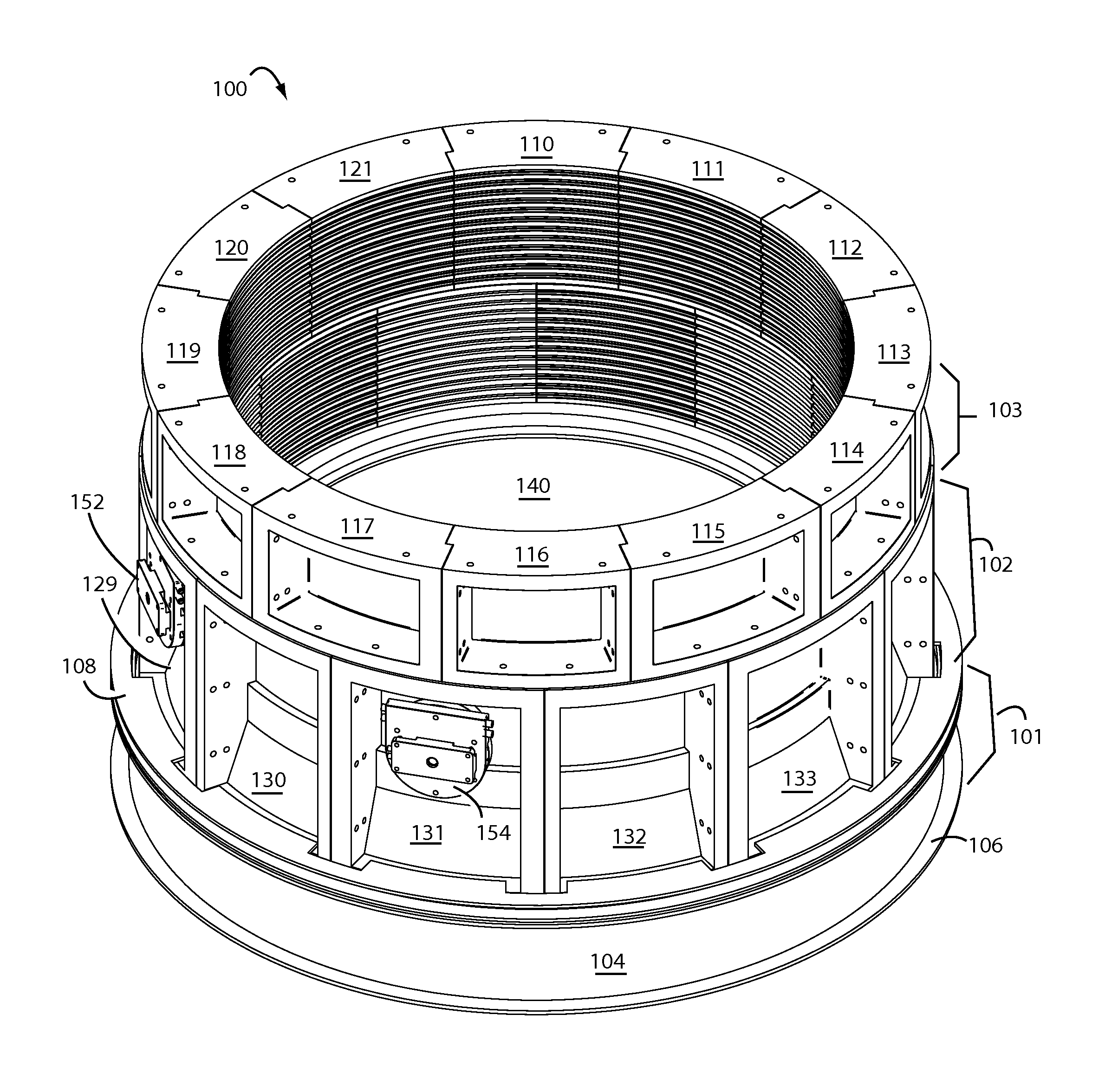
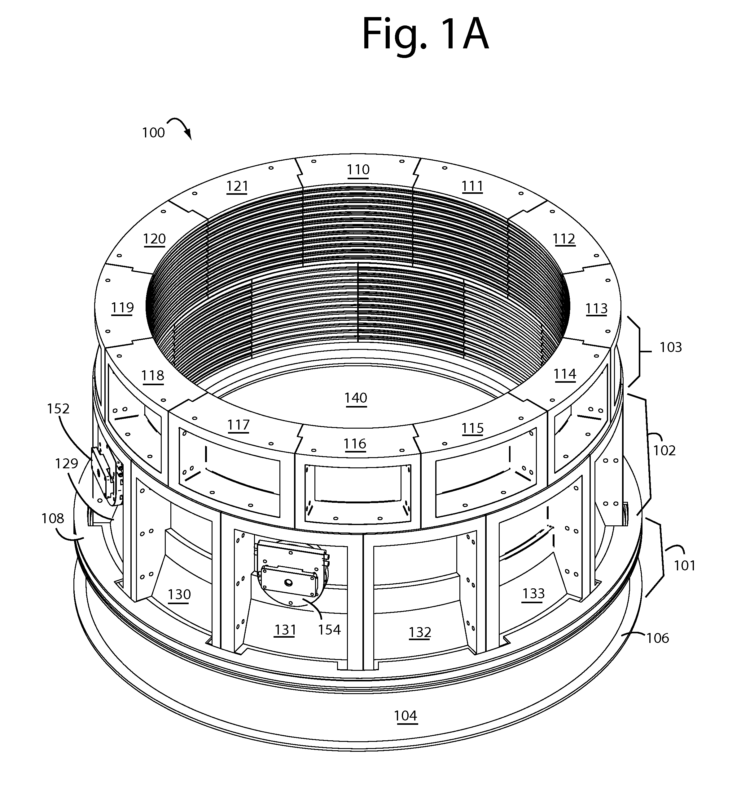
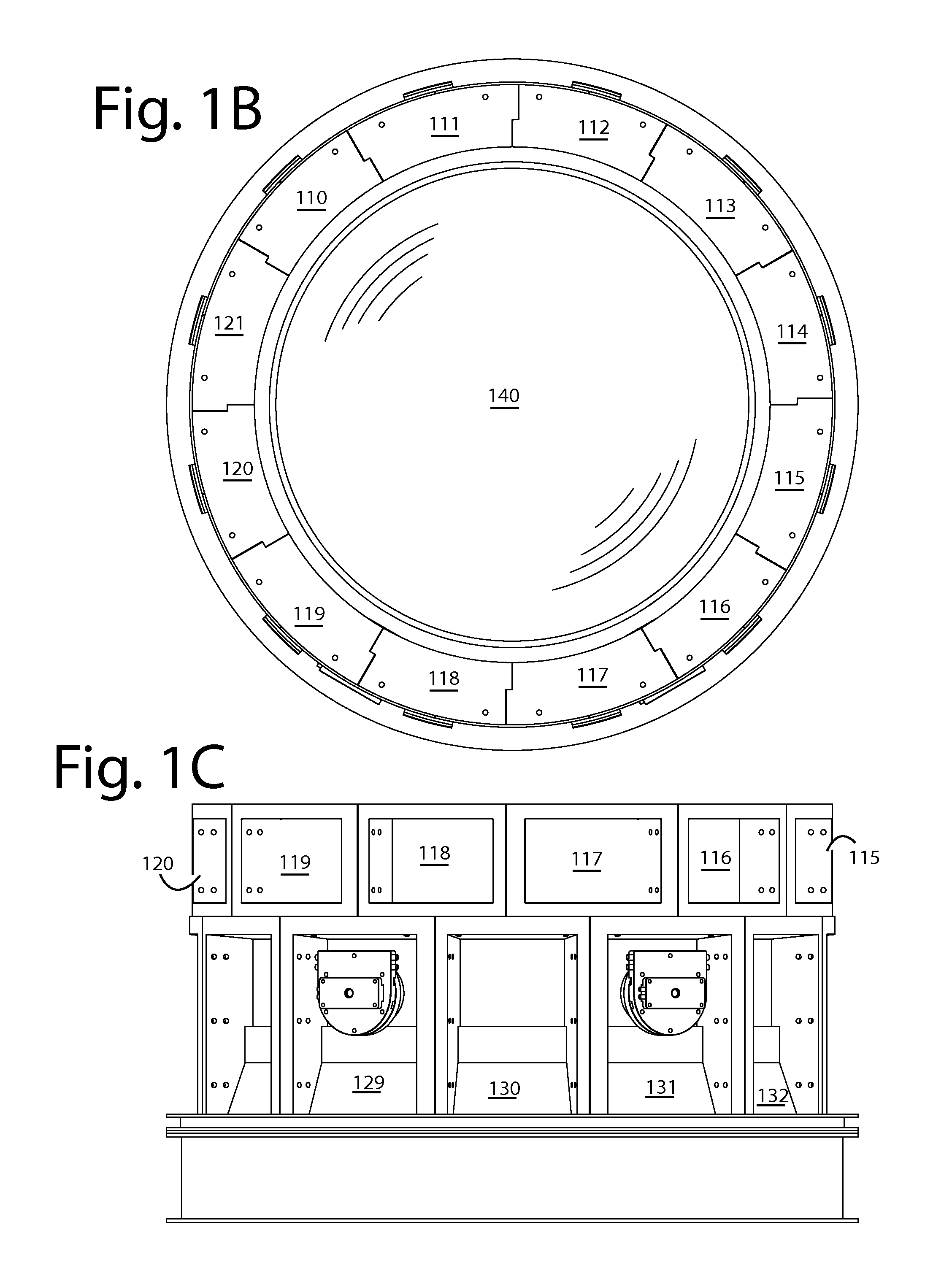
[0022]Embodiments of the present invention do not rely on a full containment shell to provide the hoop strength and leverage necessary to compress the brick hearth in a furnace refractory. The coolers themselves are cast as segments of a ring that can be stacked in tiers, and then interconnected with springs and bolts through flanges on their outer perimeters to form an elastic hoop. The assembled coolers and adjustments provide the substantial inward compressive forces required to keep the gaps and joints closed in the brick hearth and walls that line the innards.

[0023]FIGS. 1A-1D represent an elastically interconnected cooler compressed hearth embodiment of the present invention, and is referred to herein by the general reference numeral 100. Hearth 100 comprises a bottom section 101 on which a first tier 102 and a second tier 103 of segmented coolers are assembled into rings and stacked. A base 104 is provided with a footer flange 106. A hold-down ring 108 is used to clamp the fi...


PUM

PropertyMeasurementUnit
diameteraaaaaaaaaa
perimeteraaaaaaaaaa
pressuresaaaaaaaaaa

Abstract

An elastically interconnected cooler compressed hearth comprises a concave dished bottom lined with a sub-layer and a working layer of hearth bricks. Cylindrical walls that rise up from the rim of the concave dished bottom are constructed with one or more tiers of coolers shaped into arc segment blocks that are joined together by their flanges to form complete rings. The outer perimeter of the hearth brick within the ringed tiers is inwardly compressed toward the center to disallow any leaks from forming between the separate bricks. The coolers are elastically interconnected at their flanges by fasteners and springs. Each spring can be individually adjusted to obtain optimal working pressures on the whole of the core wall and hearth floor bricks.

Description

BACKGROUND[0001]1. Field of the Invention[0002]The present invention relates to round-bottom pyrometallergical furnaces for the smelting, converting, or melting of concentrates, mattes, or metals; and more particularly to elastically interconnecting coolers arranged in ring segments and tiers to optimally compress the brick hearth and lower walls in a furnace refractory without resorting to a containment shell.[0003]2. Description of the Prior Art[0004]One type of smelting furnace for winning copper from ore is built with vertical, cylindrical, steel containment shells with layers of refractory bricks inside the walls and a downwardly dished bottom. A hearth brick sub-layer on the bottom is covered with a brick hearth working layer. The refractory brick layers inside the steel containment shells can withstand the very high operating temperatures usual to the smelting of copper concentrate, and the outer shell provides the necessary containment and support.[0005]Hearth bricks swell u...

Claims


Application Information

Patent Timeline
Patent Type & Authority Applications(United States)
IPC IPC(8): F27D1/14F27D9/00
CPCF27B3/24F27D9/00F27D1/12F27D1/147Y10T29/49716F27B3/14
Inventor MACRAE, ALLAN
Owner MACRAE ALLAN
Why Eureka
Try Eureka