Pump monitoring device

a monitoring device and pump technology, applied in the direction of pumps, instruments, heat measurement, etc., can solve the problems of rotating components that gradually wear, eventually fail, and the failure of the pump can have catastrophic consequences

Active Publication Date: 2013-04-25
IOT DIAGNOSTICS LLC
View PDF11 Cites 34 Cited by
  • Summary
  • Abstract
  • Description
  • Claims
  • Application Information

AI Technical Summary

Problems solved by technology

To pressurize the fluid, the pumps have rotating components that gradually wear over time and may eventually fail if the wear is left unchecked.
Failure of the pump can have catastrophic consequences.
For example, if a pump abruptly fails, substantial debris can be introduced into the system causing damage to downstream components.
In addition, catastrophic failures can result in substantial disruption of the manufacturing process.
One problem, however, is how to objectively schedule preventive maintenance.
Because pump wear cannot be easily monitored during operation, failures may not be easily predicted.
Fluid leakage from the case drain may be due to increased leakage within the pump around and between various components and seals in the pump.
Prior art devices for measuring leakage from a case drain, however, are generally complicated in design and may be costly.
However, the disclosed device is a complicated venturi design which requires sophisticated analysis techniques and may be difficult to calibrate.
Furthermore, the disclosed design fails to provide any measurement of other parameters of the fluid power system at the case drain.
For this reason, such measurements are costly or may not be taken at all.
In view of this deficiency, the information needed to predict an impending pump failure may be missing.

Method used


Image

  • Pump monitoring device
  • Pump monitoring device
  • Pump monitoring device

Examples


Embodiment Construction

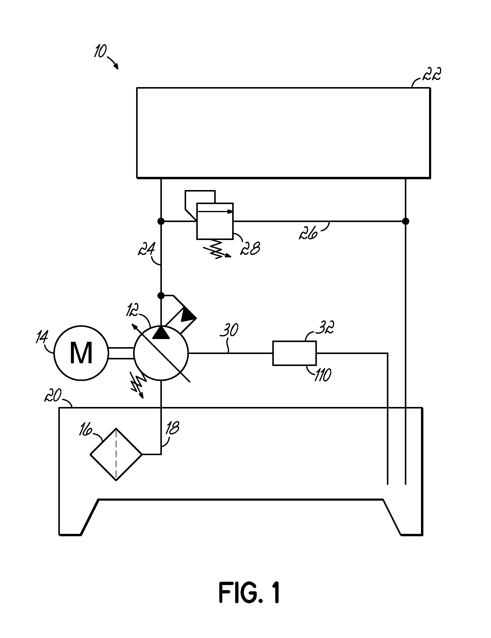
[0032]With reference to FIG. 1, an exemplary fluid power system 10 may include a variable speed hydraulic pump 12 powered by a motor 14. During operation, the pump 12 may draw fluid through a filter 16 and suction line 18 from a tank 20. The pump 12 may pressurize the fluid for use by a machine 22 in fluid communication with the pump 12 via a main line 24. The system 10 may optionally include other circuits, such as, the pressure relief circuit 26, including a relief valve 28 for relieving pressure in the system 10 in the event of a malfunction of the pump 12 or machine 22. The pump 12 may also include a case drain 30, which may drain any leakage of the fluid through the pump 12 back to the tank 20. While some fluid leakage through the case drain 30 may be normal, the flow through the case drain 30 may increase as the pump 12 wears during use.

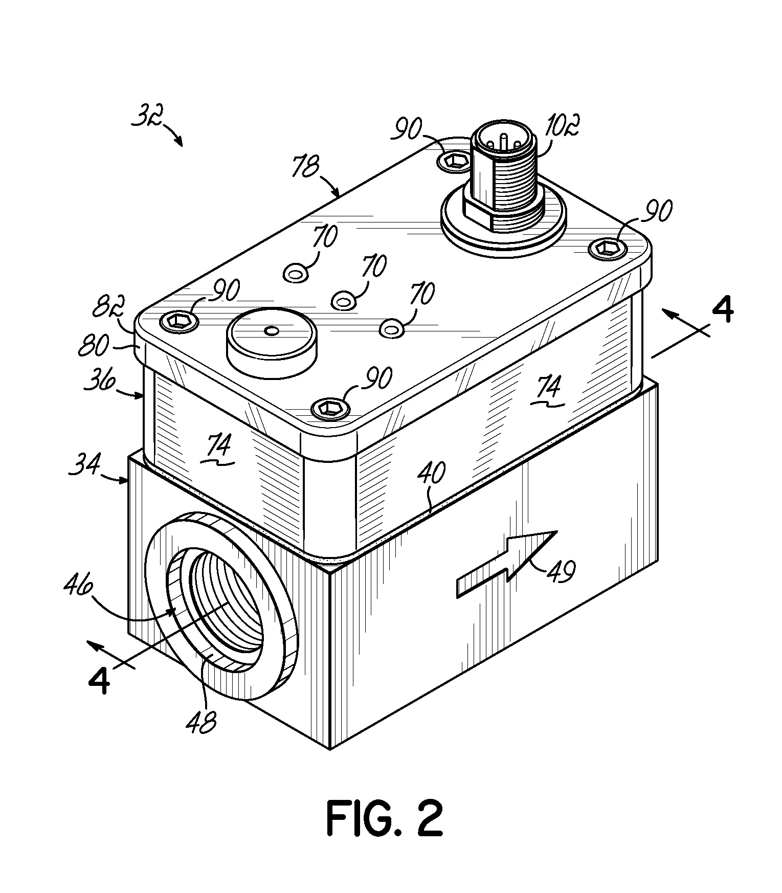
[0033]In this regard and in one embodiment of the invention, a pump monitoring device 32 is connected to the case drain 30 to measure the flow...


PUM


Abstract

A pump monitoring device is configured to be connected to a case drain of a pump. The device includes a manifold having an inlet for connection to the case drain. A flow rate sensor generates a signal indicative of a flow rate of fluid in a fluid path. The flow rate sensor includes a temperature sensor, a heater, and a sensor barrel. The heater heats the sensor barrel while in fluid communication with the fluid. A pressure sensor generates a signal indicative of a pressure of the fluid. There is at least one fault indicator operatively coupled to at least one of the flow rate sensor, the temperature sensor, and the pressure sensor. The fault indicator provides a human perceptible indication that at least one of a sensed flow rate, a sensed temperature, or a sensed pressure of the fluid flowing in the fluid path exceeds a predetermined threshold value.

Description

CROSS-REFERENCE TO RELATED APPLICATIONS[0001]This application claims the benefit of U.S. Provisional Patent Application Ser. No. 61 / 551,334, filed Oct. 25, 2011, and entitled “PUMP MONITORING DEVICE,” the disclosure of which is hereby incorporated by reference herein in its entirety.FIELD OF THE INVENTION[0002]This invention relates generally to fluid circuits and, more particularly, to a device for monitoring the operating condition of a pump in the fluid circuit.BACKGROUND OF THE INVENTION[0003]Industrial systems oftentimes utilize fluid power systems to perform work, such as, to run hydraulic motors or to extend and retract cylinders in various manufacturing or production environments, for example. These fluid power systems include fluid pumps that are used to pressurize fluid, proportionate to a resistive load, such as hydraulic fluid, in the system. To pressurize the fluid, the pumps have rotating components that gradually wear over time and may eventually fail if the wear is l...

Claims


Application Information

Patent Timeline
Patent Type & Authority Applications(United States)
IPC IPC(8): G08B21/18
CPCF04B2201/0405F04B49/06F04B49/10F04B51/00G01K2013/026F04B2207/701F04B2207/702F04D15/0088G01K13/02G01F1/06G01K13/026G01F1/34G01F1/69G01F15/06G01F15/14G01L19/12G08B21/187
Inventor WETHERILL, REX A.RASMUSSEN, JOHNJONES, PETER R.
Owner IOT DIAGNOSTICS LLC
Why Eureka
Try Eureka