Random jitter beamforming method and transmitter and receiver using the same

Inactive Publication Date: 2013-04-25
ELECTRONICS & TELECOMM RES INST
View PDF5 Cites 12 Cited by
  • Summary
  • Abstract
  • Description
  • Claims
  • Application Information

AI Technical Summary

Benefits of technology

The patent describes a method for reducing the impact of a side lobe in a beamforming process to achieve a narrower beam width. This method involves dividing a series of binary sequences into groups of bits, designating a beam pattern for each group of bits, and forming a beam with the designated pattern. The method can also be used in a transmitter and a receiver for RF signals. The technical effect of this method is to improve the accuracy and reliability of beamforming in RF communication systems.

Problems solved by technology

However, conventional beamforming schemes have a limitation in obtaining high beam resolution for reducing a beam width.

Method used


Image

  • Random jitter beamforming method and transmitter and receiver using the same
  • Random jitter beamforming method and transmitter and receiver using the same
  • Random jitter beamforming method and transmitter and receiver using the same

Examples


Embodiment Construction

[0031]The following description is provided to assist the reader in gaining a comprehensive understanding of the methods, apparatuses, and / or systems described herein. Accordingly, various changes, modifications, and equivalents of the methods, apparatuses, and / or systems described herein will be suggested to those of ordinary skill in the art. Also, descriptions of well-known functions and constructions may be omitted for increased clarity and conciseness.

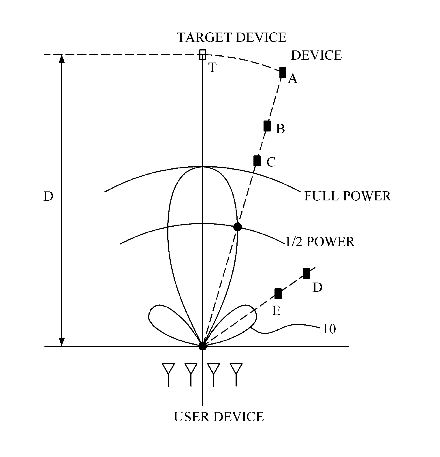
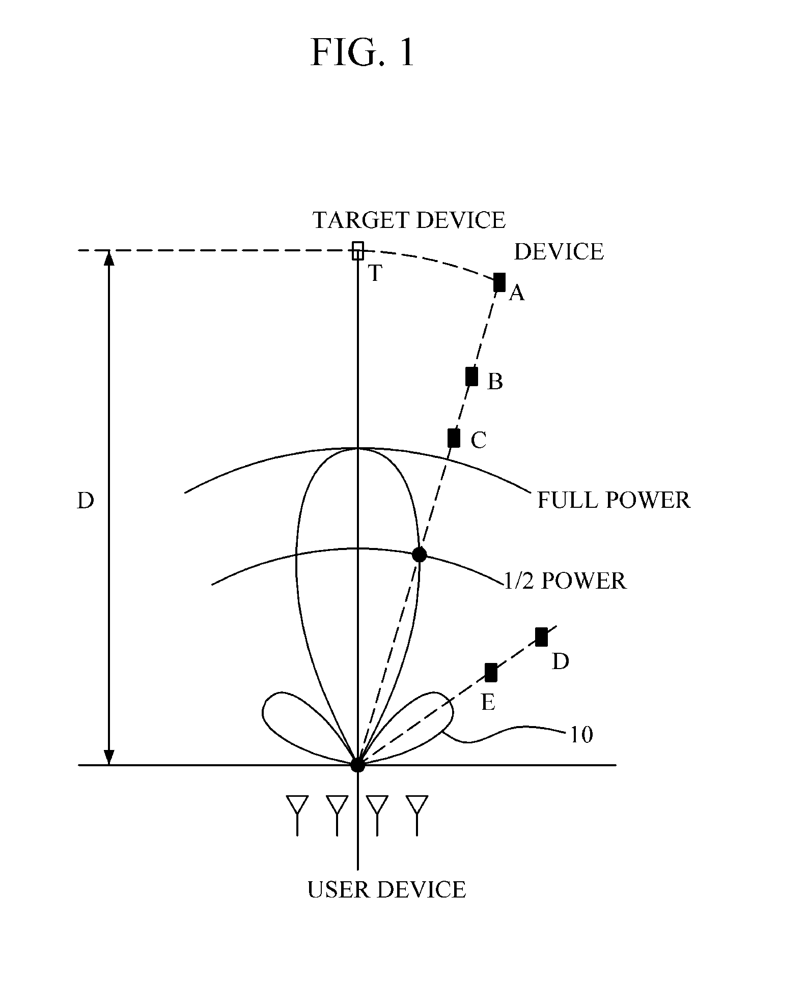
[0032]FIG. 1 is a diagram illustrating a relationship between a transmission beam pattern and devices with respect to positions of the devices.

[0033]In FIG. 1, an equidistant linear antenna array including four antennas is used.

[0034]In FIG. 1, it is assumed that devices A to C have a ½ power gain and devices D and E are disposed in a direction of a side lobe 10.

[0035]For simplification of a description, when the loss of a free-space path is assumed, the devices B and D have the same received signal strength (RSS) as a target devi...


PUM


Abstract

A random jitter beamforming method for reducing the influence of a side lobe to decrease a beam width, and a transmitter and a receiver using the same are provided. The random jitter beamforming method includes dividing a series of binary sequences to generate a plurality of bit groups, designating a beam pattern, corresponding to each of the bit groups, from a set of two or more beam patterns having the same gain and phase in a target direction, and forming a beam with the corresponding beam pattern, for each of the bit groups.

Description

CROSS-REFERENCE TO RELATED APPLICATION[0001]This application claims priority from and the benefit under 35 U.S.C. §119(a) of Korean Patent Application Nos. 10-2011-0108234, filed on Oct. 21, 2011, 10-2012-0117389, filed on Oct. 22, 2012, the entire disclosures of which are incorporated herein by references for all purposes.BACKGROUND[0002]1. Field[0003]The following description relates to beamforming technology, and more particularly, to a random jitter beamforming method for reducing the influence of a side lobe to achieve an effect of decreasing a beam width, and to a transmitter and a receiver using the same.[0004]2. Description of the Related Art[0005]Beamforming denotes technology in which, by concentrating energy (which is radiated from an antenna) in a specific direction in a space, a receiver receives a signal in a desired direction, and a transmitter transmits a signal in a desired direction.[0006]Beamforming is often called spatial filtering, in which case a beam width is ...

Claims


Application Information

Patent Timeline
IPC IPC(8): H01Q3/38
CPCH04B7/0617H01Q3/26H04B7/086
Inventor KWAK, BYUNG-JAE
Owner ELECTRONICS & TELECOMM RES INST
Why Eureka
Try Eureka