Method and apparatus for polarization imaging

a polarization imaging and apparatus technology, applied in the field of polarization imaging apparatus, can solve the problems of inability to realize the imaging of an instantaneous three-dimensional structure, take a long time to complete, and it is difficult to observe the changes in chemical structure over time at different depth positions

Inactive Publication Date: 2013-04-25
NAT UNIV KYOTO INST OF TECH
View PDF3 Cites 50 Cited by
  • Summary
  • Abstract
  • Description
  • Claims
  • Application Information

AI Technical Summary

Benefits of technology

[0049]A polarization imaging apparatus of the present invention includes: at least one light source for supplying reference light and object light; an image pickup section capturing images of interference figures each formed from the reference light and the object light that reaches the image pickup section through an object; a reconstructed-image-producing section producing reconstructed images; and a polarized-light-image-calculating section obtaining polarized-light images, wherein: the object light and the reference light each include a first polarized-light component polarized in a first direction and a second polarized-light component polarized in a second direction that is different from the first direction, both of which object light and reference light enter the image pickup section; the image pickup section simultaneously captures an image of an interference pattern including (i) a first interference figure formed by interference between the object light and the reference light which has the first polarized-light component and a first phase, (ii) a second interference figure formed by interference between the object light and the reference light which has the first polarized-light component and a second phase, (iii) a third interference figure formed by interference between the object light and the reference light which has the second polarized-light component and the first phase, and (iv) a fourth interference figure formed by interference between the object light and the reference light which has the second polarized-light component and the second phase; the reconstructed-image-producing section (I) produces a first reconstructed image of the object in regard to the first polarized-light component, after (a) extraction of pixels corresponding to the first interference figure and the second interference figure from the interference pattern and (b) pixel interpolation and (II) produces a second reconstructed image of the object in regard to the second polarized-light component, after (a) extraction of pixels corresponding to the third interference figure and the fourth interference figure from the interference pattern and (b) pixel interpolation; and the polarized-light-image-calculating section obtains the polarized-light images from the first reconstructed image and the second reconstructed image, the polarized-light images corresponding to respective positions in each of the reconstructed images of the object.
[0050]For example in the simplest example case that involves two types of polarized light and two phase levels and employs one light source, a polarization imaging apparatus includes: a light source supplying reference light and object light; an image pickup section capturing images of interference figures each formed from the reference light and the object light that reaches the image pickup section through an object; a reconstructed-image-producing section producing reconstructed images; and a polarized-light-image-calculating section obtaining polarized-light images, wherein: the object light and the reference light each include a first polarized-light component polarized in a first direction and a second polarized-light component polarized in a second direction that is different from the first direction, both of which object light and reference light enter the image pickup section; the image pickup section simultaneously captures an image of an interference pattern including four types of interference images in total, the four types of interference images being (i) first and second interference figures each formed by interference between the object light and the reference light with one of two different phases, in regard to the first polarized-light component, and (ii) third and fourth interference figures each formed by interference between the object light and the reference light with one of the two different phases, in regard to the second polarized-light component; the reconstructed-image-producing section (I) produces a first reconstructed image of the object in regard to the first polarized-light component, after (a) extraction of pixels corresponding to the first and second interference figures from the interference pattern and (b) pixel interpolation and (II) produces a second reconstructed image of the object in regard to the second polarized-light component, after (a) extraction of pixels corresponding to the third and fourth interference figures from the interference pattern and (b) pixel interpolation; and the polarized-light-image-calculating section obtains the polarized-light images from the first reconstructed image and the second reconstructed image, the polarized-light images corresponding to respective positions in each of the reconstructed images of the object.
[0051]Accordingly, it is possible to (i) simultaneously obtain four types of interference figures for different optical path lengths or reference light that has different phases and different polarization directions, and to (ii) obtain a reconstructed image for each polarization direction by an optical-path-length shift method or a phase shift method. From the reconstructed image, a polarization state of the object light at each position of the reconstructed image of the object can be obtained. This makes it possible to eliminate the need for capturing images multiple times and to obtain detailed three-dimensional information and polarized light distributions of a large area of the object by one image pickup.
[0052]The above explanatory case involves two polarization directions and two types of optical path lengths, that is, phase differences. For this combination, the minimum number of types of interference figures simultaneously captured is four. Even when four or more types of interference figures are simultaneously captured for a combination of two or more types of polarization directions and two or more types of optical path lengths, that is, phase differences phases, imaging of an instantaneous three-dimensional structure and polarized-light distributions of an object can be similarly performed. By using two or more light sources, imaging of an instantaneous three-dimensional structure, and polarized-light distributions, and spectral characteristics of an object can be performed.

Problems solved by technology

However, the above-mentioned polarization imaging techniques cannot realize imaging of an instantaneous three-dimensional structure because of, for example, the following reasons.
Therefore, (i) it takes long to complete a product inspection because images should be taken multiple times, (ii) it is very difficult to observe how chemical structures change over time at different depth positions, and (iii) it is very difficult to observe, via a motion picture, how metabolite or the like behaves that is three-dimensionally spread in a living body (cell).

Method used


Image

  • Method and apparatus for polarization imaging
  • Method and apparatus for polarization imaging
  • Method and apparatus for polarization imaging

Examples


embodiment 1

[0109]The following discusses in detail Embodiment 1, with reference to FIGS. 1 through 8. In Embodiment 1, the number of light sources is 1; in regard to reference light, the number of light components polarized in different directions is 2; and in regard to light components polarized in first and second directions, the number of different phases is 2.

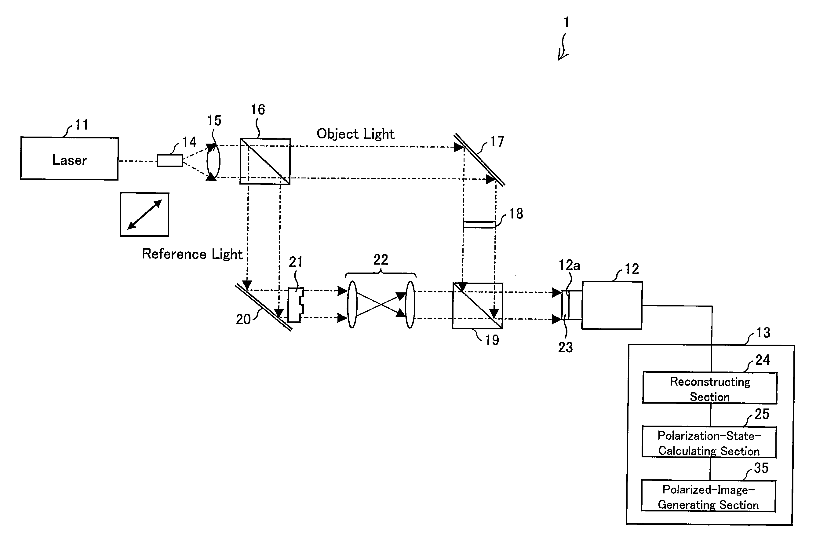
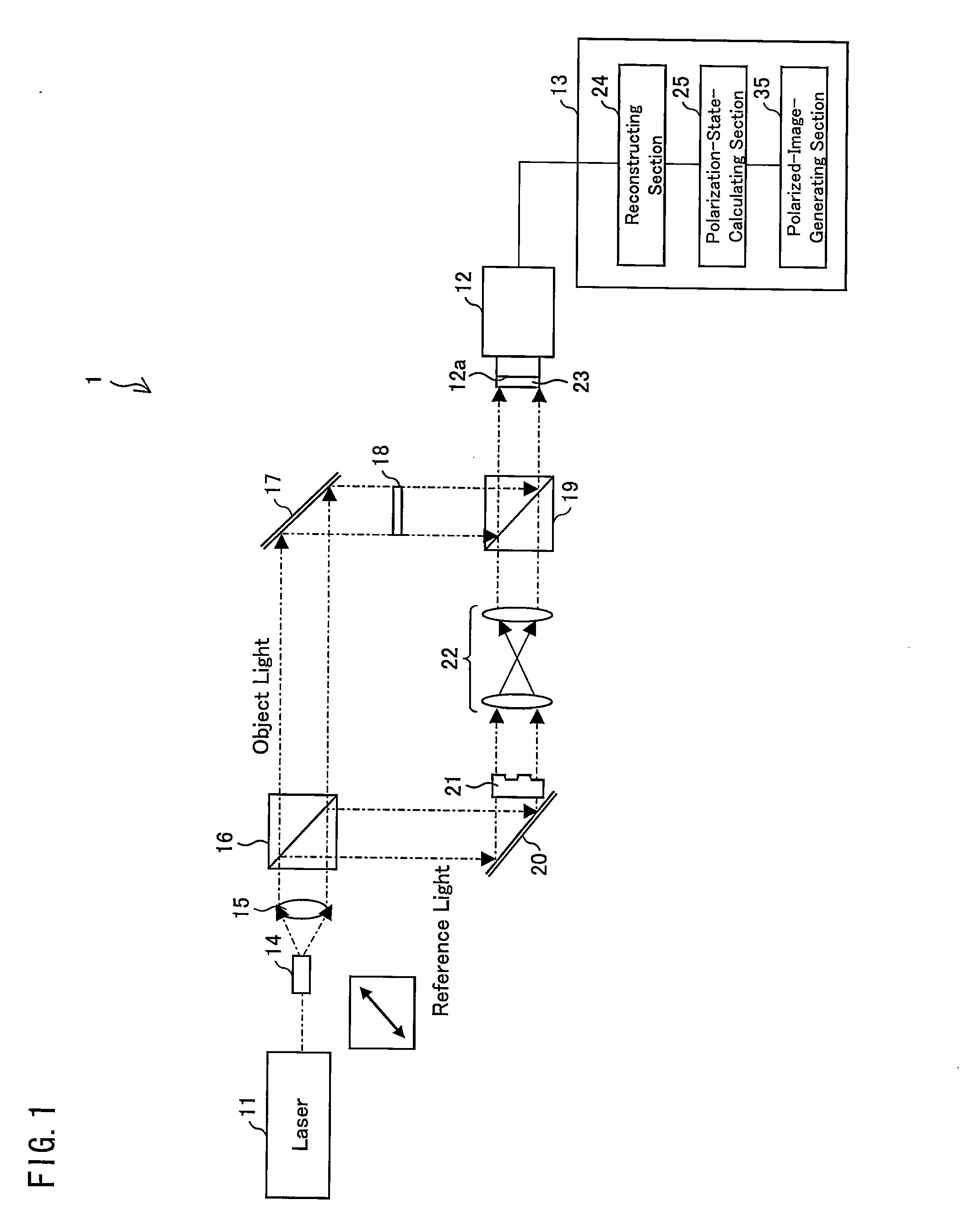
[0110]FIG. 1 is a view schematically illustrating a polarization imaging apparatus 1 according to Embodiment 1 of the present invention. The polarization imaging apparatus 1 includes an image pickup device including an optical system provided with a laser light source (light source) 11 and an image pickup element (image pickup section) 12. The image pickup element 12 has an image pickup plane 12a which is made of a CCD. Further, the polarization imaging apparatus 1 includes a computer 13 connected to an output of the image pickup element 12. The image pickup element 12 has a polarizer-array device 23 disposed in front of the image pic...

embodiment 2

[0147]The following discusses in detail Embodiment 2 with reference to FIGS. 9 and 10. In Embodiment 2, the number of light sources is 1; in regard to reference light, the number of light components polarized in different directions is 2; and in regard to light components polarized in first and second directions, the number of different phases is 2. For convenience, members and configurations having the same functions as those discussed in Embodiment 1 are given identical reference signs and only explanations of differences from Embodiment 1 are given below.

[0148]FIG. 9 is a view schematically illustrating a configuration of a polarization imaging apparatus 2 according to Embodiment 2. The polarization imaging apparatus 2 includes a laser light source 11. The laser light source 11 emits linearly-polarized laser light that includes a light component polarized in the second direction (vertical direction). The polarization imaging apparatus 2 includes a ½ wave plate 36 that regulates a...

embodiment 3

[0167]The following discusses in detail Embodiment 3 with reference to FIG. 11. In Embodiment 3, the number of light sources is 1; in regard to reference light, the number of light components polarized in different directions is 2; and in regard to light components polarized in first and second directions, the number of different phases 2. For convenience, members and configurations having the same functions as those discussed in Embodiment 1 are given identical reference signs and only explanations of differences from Embodiment 1 are given below. Embodiment 3 discusses application to a polarization microscope that is suitably used for observation of living samples such as cells.

[0168]FIG. 11 is a view schematically illustrating a configuration of a polarization imaging apparatus 3 of Embodiment 3 of the present invention. A laser light source 11 of the polarization imaging apparatus 3 emits laser light in a polarization direction that is inclined at 45° relative to a first directi...


PUM


Abstract

A polarization imaging apparatus includes a laser light source and an image pickup element. Object light and reference light each include a first polarized-light component polarized in a first direction and a second polarized-light component polarized in a second direction that is different from the first direction. The image pickup element simultaneously captures an image of an interference pattern including (i) a first interference figure, (ii) a second interference figure, (iii) a third interference figure, and (iv) a fourth interference figure. The polarization imaging apparatus includes a reconstructing section generating respective reconstructed images of the object in regard to the first and second polarized-light components, from the first to fourth interference figures, and a polarized-light-image-calculating section obtaining polarized-light images from the reconstructed images.

Description

TECHNICAL FIELD [0001]The present invention relates to a polarization imaging apparatus and a polarization imaging method each of which is for performing polarization imaging of an object.BACKGROUND ART [0002]In the following descriptions, radian is used as a unit for phases. In recent years, there has been developed a polarization imaging camera that simultaneously obtains information on polarization in a plurality of directions. As a result, proposals are made for a polarization imaging apparatus for visualizing a polarized-light distribution of an object (Patent Literature 1) and a polarization microscope for visualizing a polarized-light distribution of an object (Patent Literature 2). Possible applications of polarization imaging are wide-ranging. Examples of such possible applications encompass (i) measurement of a structure of and / or a distortion of a material such as film or glass, which is used as a window material, a shop window, a display or the like, (ii) measurement of ...

Claims


Application Information

Patent Timeline
Patent Type & Authority Applications(United States)
IPC IPC(8): H04N5/225
CPCG03H1/0443G03H2001/0458G03H2001/2276G01N2021/1765H04N5/2256G01N21/21G03H2222/31H04N23/56
Inventor AWATSUJI, YASUHIROTAHARA, TATSUKI
Owner NAT UNIV KYOTO INST OF TECH
Why Eureka
Try Eureka