Lighting device and display device

Active Publication Date: 2013-04-25
SHARP KK
View PDF7 Cites 1 Cited by
  • Summary
  • Abstract
  • Description
  • Claims
  • Application Information

AI Technical Summary

Benefits of technology

[0027]According to the present invention, there can be obtained a lighting device and a display device whereby

Problems solved by technology

However, cold cathode fluorescent lamps, when employed as light sources in backlight units, entail some inconvenience in that emission luminance and

Method used


Image

  • Lighting device and display device
  • Lighting device and display device
  • Lighting device and display device

Examples


Example

[0035]The features of a display device outfitted with a lighting device according to an embodiment of the present invention is described with reference to FIGS. 1 to 6.

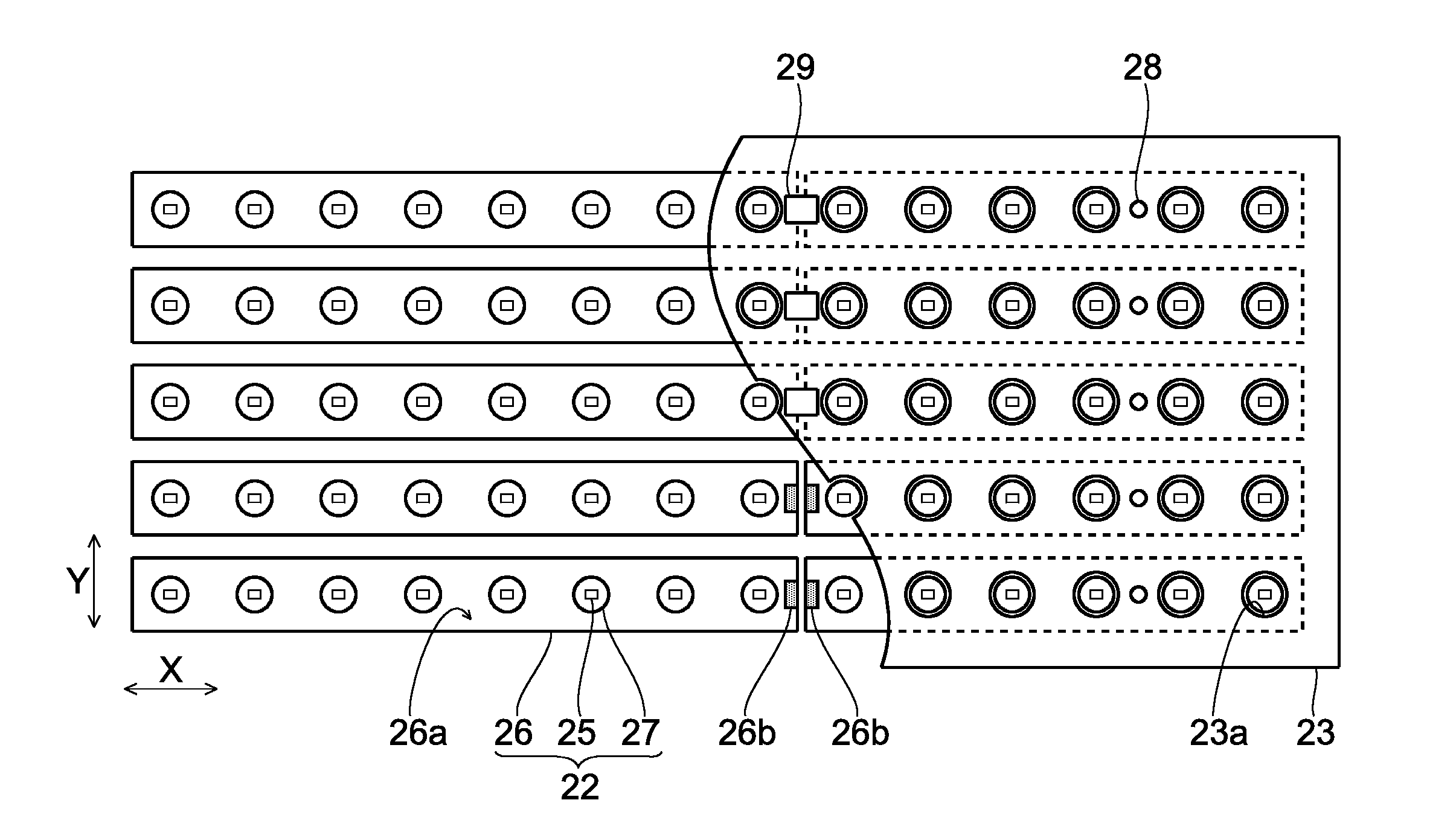
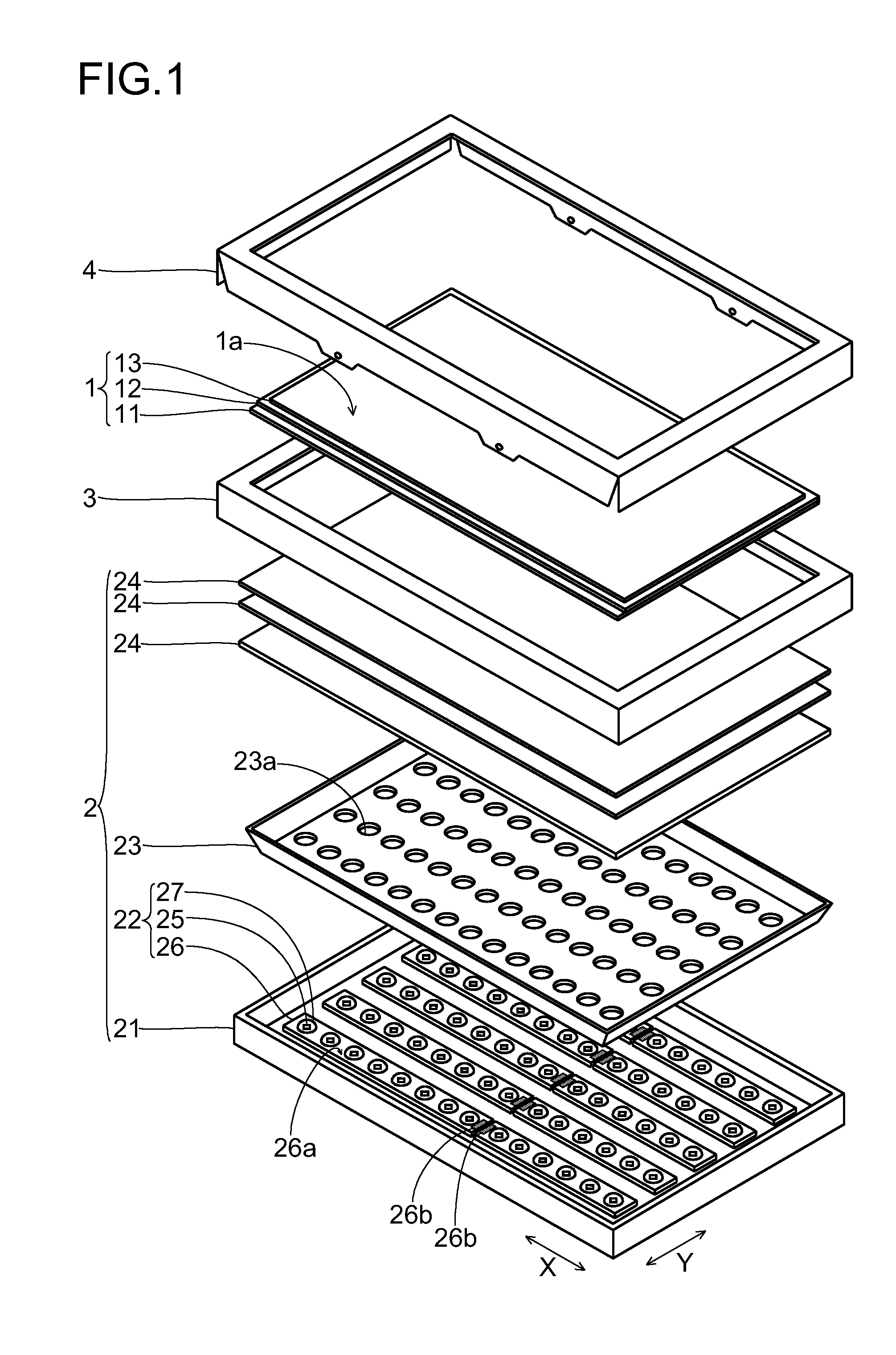
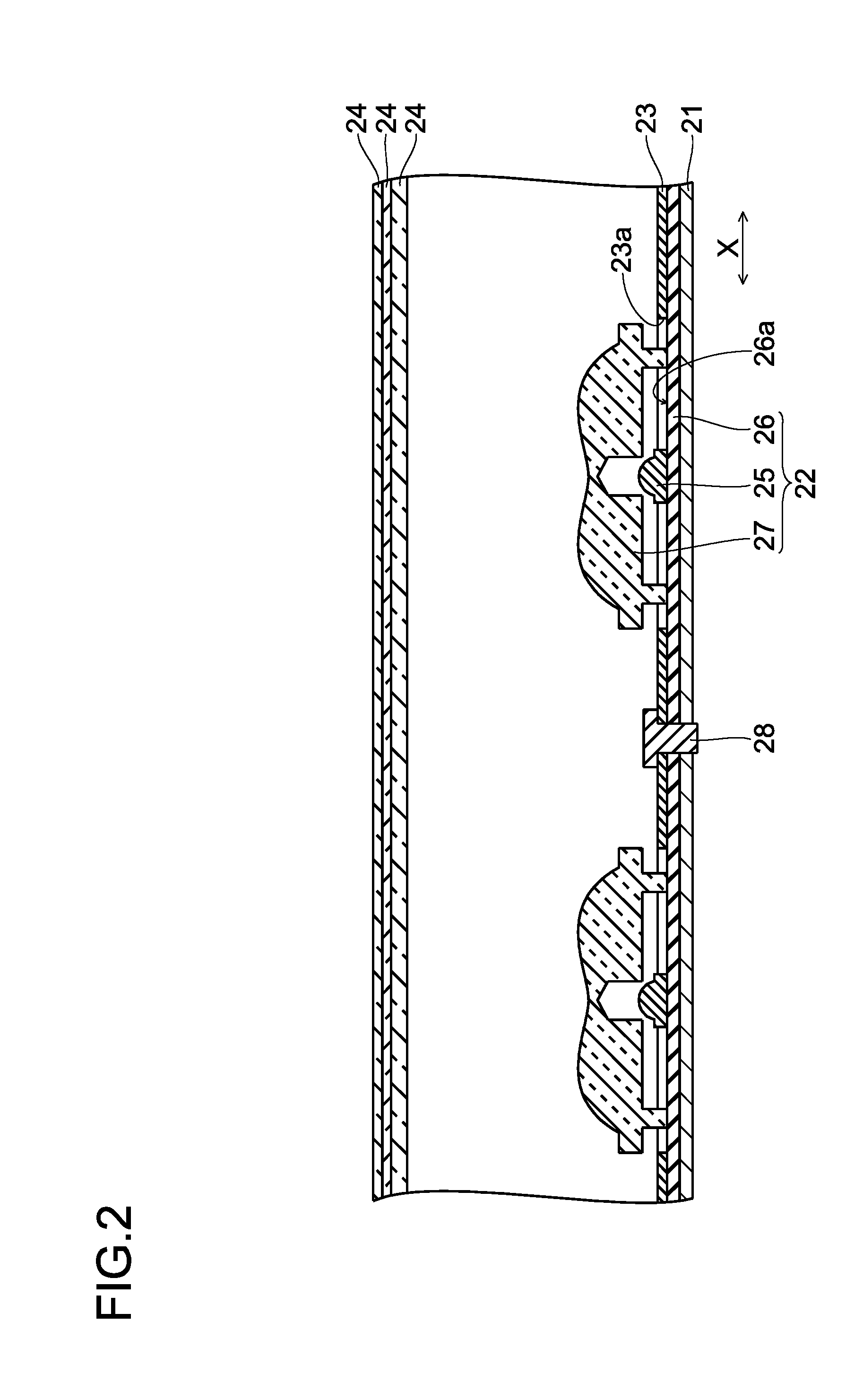
[0036]This display device is a liquid crystal display device suitable for incorporation into various devices (for example, television receiver devices or the like), and, as shown in FIG. 1, is equipped at a minimum with a liquid crystal display panel 1 having a display surface 1a for displaying images, and a backlight unit 2 outfitted to the back surface side of the liquid crystal display panel 1a, which lies at the opposite side from the display surface 1a. The liquid crystal display panel 1 is an example of the “display panel” of the present invention, and the backlight unit 2 is an example of the “lighting device” of the present invention.

[0037]The liquid crystal display panel 1 has a display area in which images are actually displayed; and a non-display area, which is an area at the outside edge of the display are...


PUM


Abstract

A lighting device includes LEDs, a reflecting sheet that reflects light emitted from the LEDs, and connectors electrically connected to the LEDs. The reflecting sheet has integrated superposed portions on which the connectors are superposed, and the connector surface on the reflecting sheet side thereof serves as a sheet pressing surface for pressing down the superposed portions of the reflecting sheet.

Description

TECHNICAL FIELD[0001]The present invention relates to a lighting device and a display device.BACKGROUND ART[0002]In a liquid crystal display device, which is one type of display device, the liquid crystal display panel is non-luminescent, and therefore a separate lighting device is provided to the back face side (the side opposite from the display face side of the liquid crystal display panel) of the liquid crystal display panel. During display operation, the lighting device lights the back face of the liquid crystal display panel, whereby an image is displayed on the display face of the liquid crystal display panel. A lighting device outfitted to a liquid crystal display device is termed a backlight unit, for example.[0003]It is known to use a cold cathode fluorescent lamp in which mercury or xenon is sealed in the interior of a fluorescent tube, as a light source in a backlight unit. However, cold cathode fluorescent lamps, when employed as light sources in backlight units, entail...

Claims


Application Information

Patent Timeline
IPC IPC(8): F21V7/10
CPCG02F1/133605G02F1/133608G02F1/133603G02F2001/133612H01R25/162G02F1/133611G02F1/133612
Inventor MATSUI, KEITARO
Owner SHARP KK
Why Eureka
Try Eureka