Tape head with facing beams each having a head chip positioned in a recess thereof

a tape head and face beam technology, applied in the field of magnetic heads, can solve the problems of limited number of individual dies which contain the read/write recording devices that can be cut from each wafer, the operating efficiency of disk heads and tape heads is inherently different, and the operation speed of tape drives is approximately 3 to 6 meters per second. , to achieve the effect of high utilization of available real estate area

Inactive Publication Date: 2012-09-11
INT BUSINESS MASCH CORP
View PDF18 Cites 1 Cited by
  • Summary
  • Abstract
  • Description
  • Claims
  • Application Information

AI Technical Summary

Benefits of technology

[0008]The present invention overcomes the drawbacks and limitations described above by providing a head that has high utilization of available real estate area on the wafer while solving problems previously associated with manufacture of partial span heads by eliminating the requirement of aligning the closure to beam skiving edges proximate to the tape closure.
[0009]The invention generally uses the second method of fabricating a partial span head describe above, including aligning the substrate portion of the chip to the beam. However, the closure is allowed to project upwards into the otherwise planar tape surface, which the inventors have surprisingly found does not cause a problem when reading and writing to the tape. This allows the head to be built and cabled far more easily than the methods described above. In order to minimize the irregularity imposed by the closure sticking out, the closure is made as short as possible and the angle between the two modules (beam and chip) as shallow as possible (there are limits of course).
[0010]The heads described herein they have good durability. Further, it is not necessary to provide tape support immediately proximate to the closure pieces.
[0011]Accordingly, a tape head according to one embodiment includes first and second beams each having a recess in a tape bearing surface thereof and a face, where the faces of two the beams either face each other or face away from each other. A first chip is positioned in the recess of the first beam, and a second chip is positioned in the recess of the second beam. Each chip has circuitry selected from a group consisting of read elements, write elements, and combinations thereof. A tape bearing surface of each chip is generally aligned with the tape bearing surface of the associated beam. Also, an end of each chip is generally aligned with the face of the associated beam. Where closures are used, this eliminates the need of aligning the closure to a beam's feature.

Problems solved by technology

However, the operating efficiency of disk heads and tape heads are inherently different.
By contrast, tape stacking and other requirements limit tape drive operating speeds to approximately 3 to 6 meters per second.
A problem is that thin film wafers are of a standardized size, and thus, the number of individual dies which contain the read / write recording devices that can be cut from each wafer is limited.
However, a problem inherent in this method is that it is difficult to assemble the chip and beam with near-perfect alignment at the tape bearing surface.
It is also more difficult to attach a cable since the contacts are now recessed from the side of the beam, and conventional cable bonding tooling does not easily reach into the recess.

Method used


Image

  • Tape head with facing beams each having a head chip positioned in a recess thereof
  • Tape head with facing beams each having a head chip positioned in a recess thereof
  • Tape head with facing beams each having a head chip positioned in a recess thereof

Examples


Embodiment Construction

[0032]The following description is the best embodiment presently contemplated for carrying out the present invention. This description is made for the purpose of illustrating the general principles of the present invention and is not meant to limit the inventive concepts claimed herein.

[0033]The present invention provides a method and mechanism for slicing a thin film wafer to form such things as tape head components. A thin film wafer can be any type of composite or composition capable of containing circuitry therein, and includes semiconductor wafers.

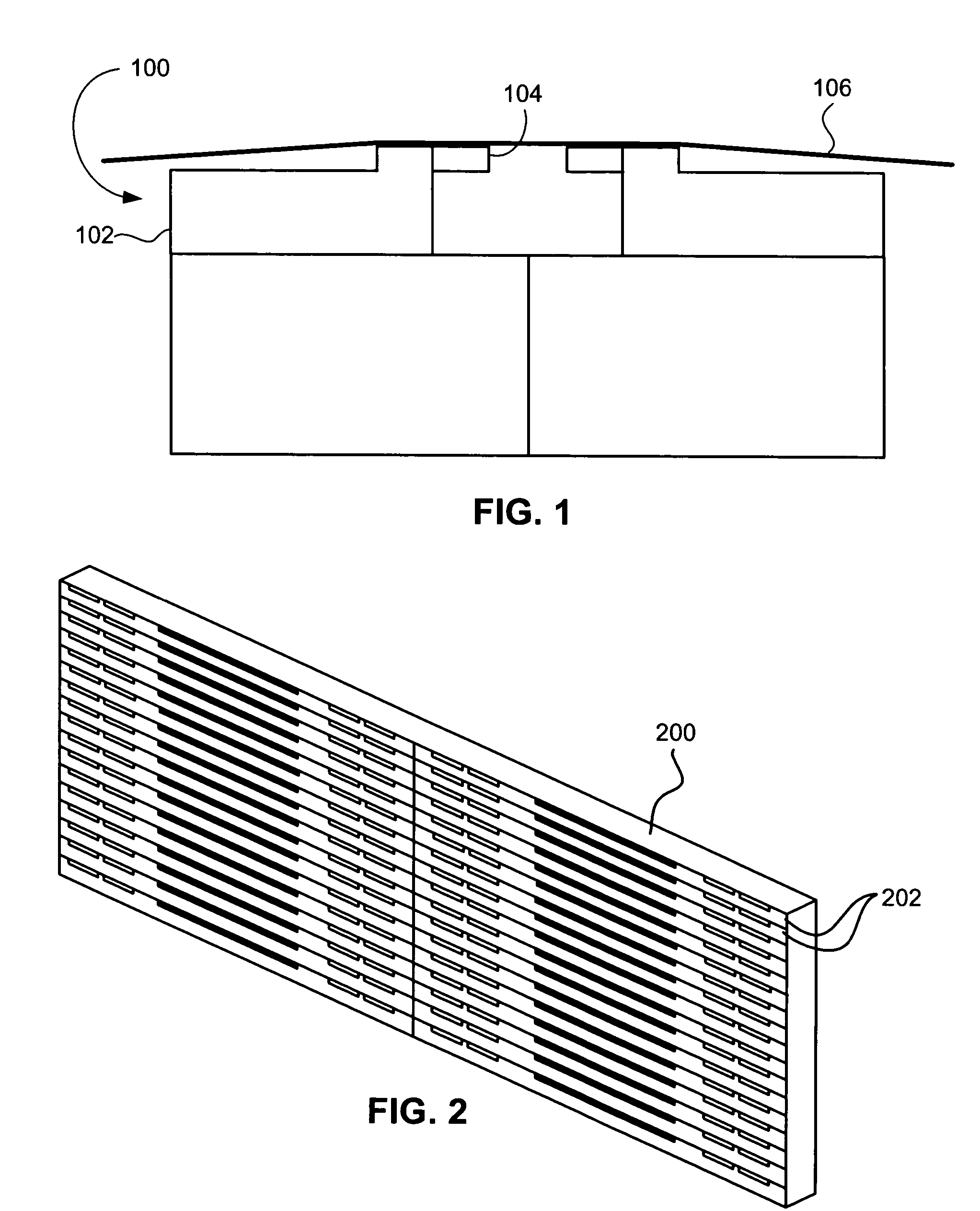
[0034]One category of component created by thin film processing is the tape head. FIG. 1 depicts one such tape head 100. The head 100 consists of a pair of head portions 102, each having a closure 104 that engages the tape 106 as it passes over the tape bearing surface of the head 100. The tape bearing surfaces angle upwardly (towards the tape) so the tape wraps both substrate and closure edges.

[0035]The invention according to a prefe...


PUM

PropertyMeasurementUnit
speedsaaaaaaaaaa
operating speedsaaaaaaaaaa
sizesaaaaaaaaaa

Abstract

A tape head has first and second beams each having a recess in a tape bearing surface thereof, a face where the faces of the beams either face each other or face away from each other. A first chip is positioned in the recess of the first beam, and a second chip is positioned in the recess of the second beam. Each chip has circuitry selected from a group consisting of read elements, write elements, and combinations thereof. A tape bearing surface of each chip is generally aligned with the tape bearing surface of the associated beam. Also, an end of each chip is generally aligned with the face of the associated beam. Where closures are used, this eliminates the need to aligning the closure to skiving edges of the beam.

Description

FIELD OF THE INVENTION[0001]The present invention relates to magnetic heads, and more particularly, this invention relates to a magnetic head having embedded chips each containing read and / or write elements.BACKGROUND OF THE INVENTION[0002]Many modern electronic components are created by thin film wafer processing. One category of component created by thin film processing is the tape head. Another category is the disk head.[0003]Most tape heads are currently built on wafers using thin film processes, similar to the wafers used for fabricating disk heads. However, the operating efficiency of disk heads and tape heads are inherently different. Disk recording / reading is very efficient, as the disk media is extremely flat and smooth, has a very thin magnetic layer, is in a sealed environment, and the heads are constructed to function with a particular media. Writing and reading tapes must address very different challenges. For example, the head must work with different tape brands, whic...

Claims


Application Information

Patent Timeline
Patent Type & Authority Patents(United States)
IPC IPC(8): G11B5/105G11B5/187G11B5/265G11B15/60G11B5/48G11B5/584G11B21/16
CPCG11B5/584
Inventor BISKEBORN, ROBERT GLENNEATON, JAMES HOWARD
Owner INT BUSINESS MASCH CORP
Why Eureka
Try Eureka