Electrical connector

a technology of electrical connectors and connectors, applied in the direction of connection contact member materials, coupling device connections, measurement leads/probes, etc., can solve the problems of unstable inspection and expensive means for such identification, and achieve the effect of minimizing irregular measurements and stable inspection of integrated circuit pads

Inactive Publication Date: 2006-03-21
THE FUJIKURA CABLE WORKS LTD
View PDF10 Cites 0 Cited by
  • Summary
  • Abstract
  • Description
  • Claims
  • Application Information

AI Technical Summary

Benefits of technology

[0009]It is an object of the invention to provide an improved electrical connector which eliminates the disadvantages of the prior art and which enables stable inspection for integrated circuit pads in a manner minimizing irregularities in measured values such as electric resistance value and skew.

Problems solved by technology

For chips obtained by individual dicing of wafers, it is required to identify front and rear faces, top and bottom, and right and left of the chip preparatory to measurement of characteristics so that expensive means for such an identification are required as well.
Consequently, there would be a tendency of irregularities in measured values such as disclosed electric resistance values and skews to occur in the inspection, resulting in unstable inspection.

Method used


Image

  • Electrical connector
  • Electrical connector
  • Electrical connector

Examples


Embodiment Construction

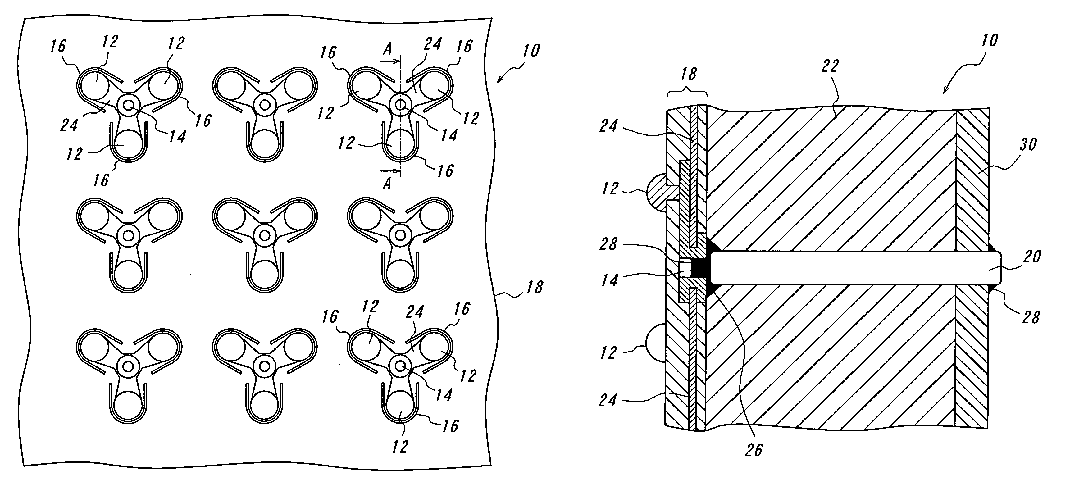
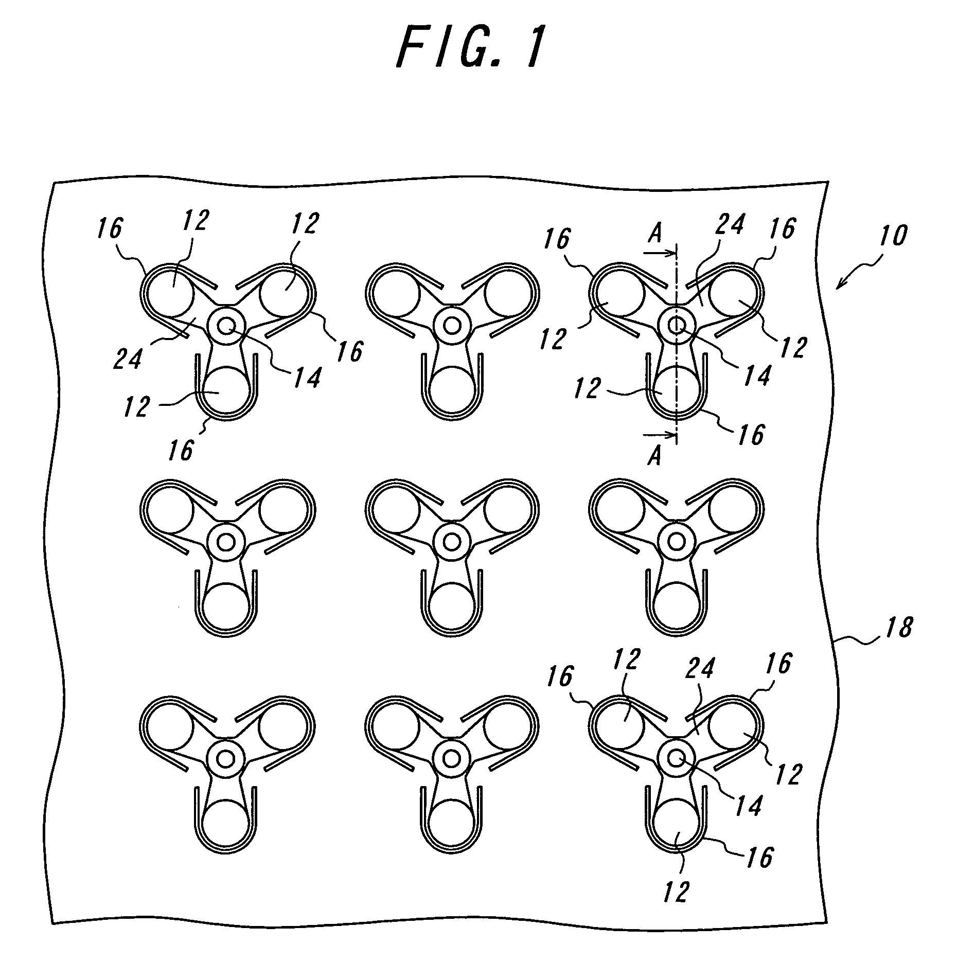
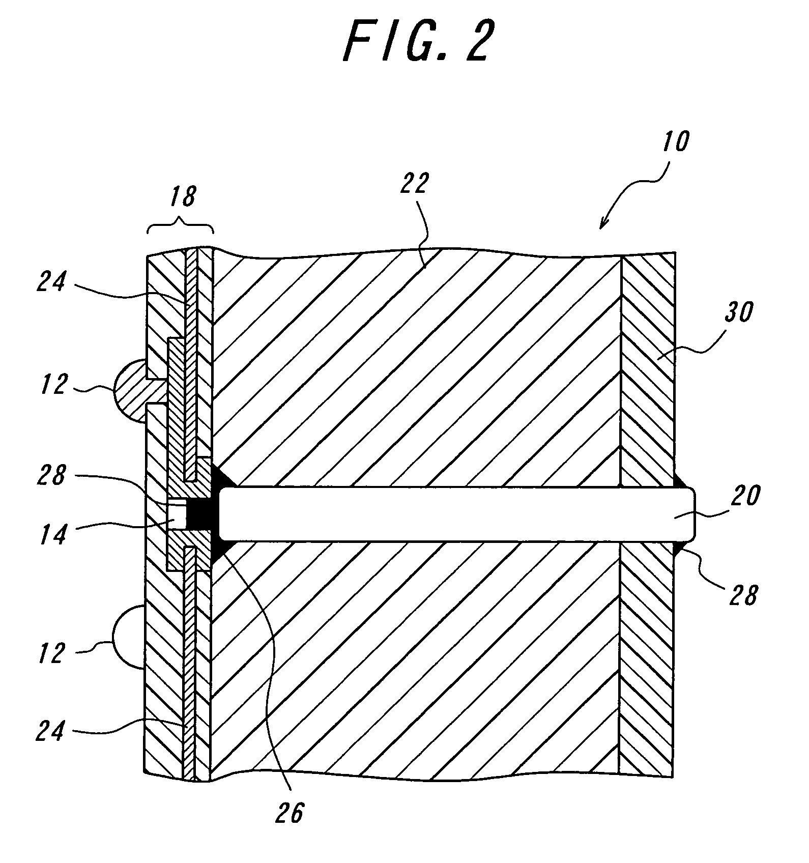
[0027]The electrical connector 10 according to the invention will be explained in detail with reference to FIGS. 1 to 3. FIG. 1 is a plan view of the connector according to the invention and FIG. 2 is a partly longitudinal sectional view of the electrical connector taken along the line A—A in FIG. 1.

[0028]FIG. 3 is a view for explaining variations in measured values caused by positional shifting of electric contacts from the center of an integrated circuit pad.

[0029]The electrical connector 10 according to the invention serves to inspect high-speed operating integrated circuits such as LGA, BGA and the like. The electrical connector 10 mainly comprises an elastomer 22, fine conductive wires 20 and a flexible printed circuit board 18.

[0030]Prior to explanation of the respective components of the connector, the high-speed operating integrated circuit to be inspected by the electrical connector 10 will be explained. The high-speed operating integrated circuit may be mounted on a board ...


PUM


Abstract

An electrical connector includes an elastomer in the form of a layer, and a plurality of fine conductive wires embedded in the elastomer and extending rectilinearly in vertical directions to front and rear surfaces of the elastomer. The fine conductive wires have an overall length substantially the same as or slightly larger than the thickness of the elastomer so that both the ends of the fine conductive wires extend from the front and rear surfaces of the elastomer. The electrical connector includes a flexible printed circuit board connected to the fine conductive wires. The flexible printed circuit board includes at least three electric contacts arranged substantially concentrically around and electrically connected to each of the fine conductive wires. With this arrangement, the electrical connector enables a stable inspection for integrated circuit pads in a manner which minimizes irregularities in repeatedly measured values of electric resistance and skew.

Description

BACKGROUND OF THE INVENTION[0001]This invention relates to an electrical connector for use in inspecting integrated circuits used in high-speed transmission as in mobile phones, and more particularly to an electrical connector capable of minimizing irregularities in measured values of electrical characteristics of integrated circuit pads even if contact points of contacts of the connector on the pads are unexpectedly shifted.[0002]In inspecting integrated circuits, a hemispherical or other shaped electrical contact provided on a connector has been brought into contact with an integrated circuit pad at a single point to perform its inspection in the past as explained in the following patent literatures. For example, in Japanese Patent Application No. 2002-228,911 (Patent Literature 1), belonging to the applicant of the present application has proposed an electrical connector which is well-adapted to high-speed transmission signals and enables a reliable connection between fine conduc...

Claims


Application Information

Patent Timeline
Patent Type & Authority Patents(United States)
IPC IPC(8): H01R12/00G01R1/06H01R11/01H01R13/24H01R33/76
CPCH01R13/2414
Inventor OHTSUKI, TOMONARIOZAI, KAZUYUKI
Owner THE FUJIKURA CABLE WORKS LTD
Why Eureka
Try Eureka