Sealing Foil with Pull Tab

a pull tab and sealing foil technology, applied in the field of sealing foils, can solve the problems of reducing the force applied to each individual wing, reducing the risk of tab delamination or foil ripping, and not ensuring that tearing takes place as intended, so as to facilitate the handling process, improve the location of the tear line with respect to the access opening, and ensure the effect of tearing

Inactive Publication Date: 2018-10-25
NV NUTRICIA
View PDF7 Cites 0 Cited by
  • Summary
  • Abstract
  • Description
  • Claims
  • Application Information

AI Technical Summary

Benefits of technology

[0022]The invention still further relates to a method of manufacturing a package, comprising: providing a tub having a base and a sidewall defining a product containing space, the sidewall terminating in a peripheral flange defining an access opening to the space; filling the space with a quantity of powdered nutritional product; providing a web of laminate material comprising at least a barrier layer and a cover layer; partially cutting through the laminate material to form a tear line extending through at least the cover layer, the tear line defining a tear strip having a pull tab and a removable panel, encircled by a border; connecting a section of the laminate material to the tub by joining the border to the peripheral flange to seal the package, whereby the tear strip overlies the access opening; and separating the section of laminate material from the web. The provision of sections of laminate material as parts of a web for sealing of containers or tubs allows for more convenient handling of the process and also more accurate positioning of the web. Location of the tear line with respect to the access opening can thus be improved. In certain embodiments, the separation of the sections of laminate material from the web will take place after sealing of the tub. In other embodiments, these actions may take place almost simultaneously e.g in a single process.

Problems solved by technology

Firstly, the very requirement of providing a plurality of wings, reduces the force applied to each individual wing.
A user grasping a single tab may be inclined to pull the tab sideways with a component in the plain of the foil, risking delamination of the tab or ripping of the foil.
Even though the cover layer may be provided with a tear line, as many users of packages will be aware, this may not itself ensure that tearing takes place as intended.

Method used


Image

  • Sealing Foil with Pull Tab
  • Sealing Foil with Pull Tab
  • Sealing Foil with Pull Tab

Examples


Embodiment Construction

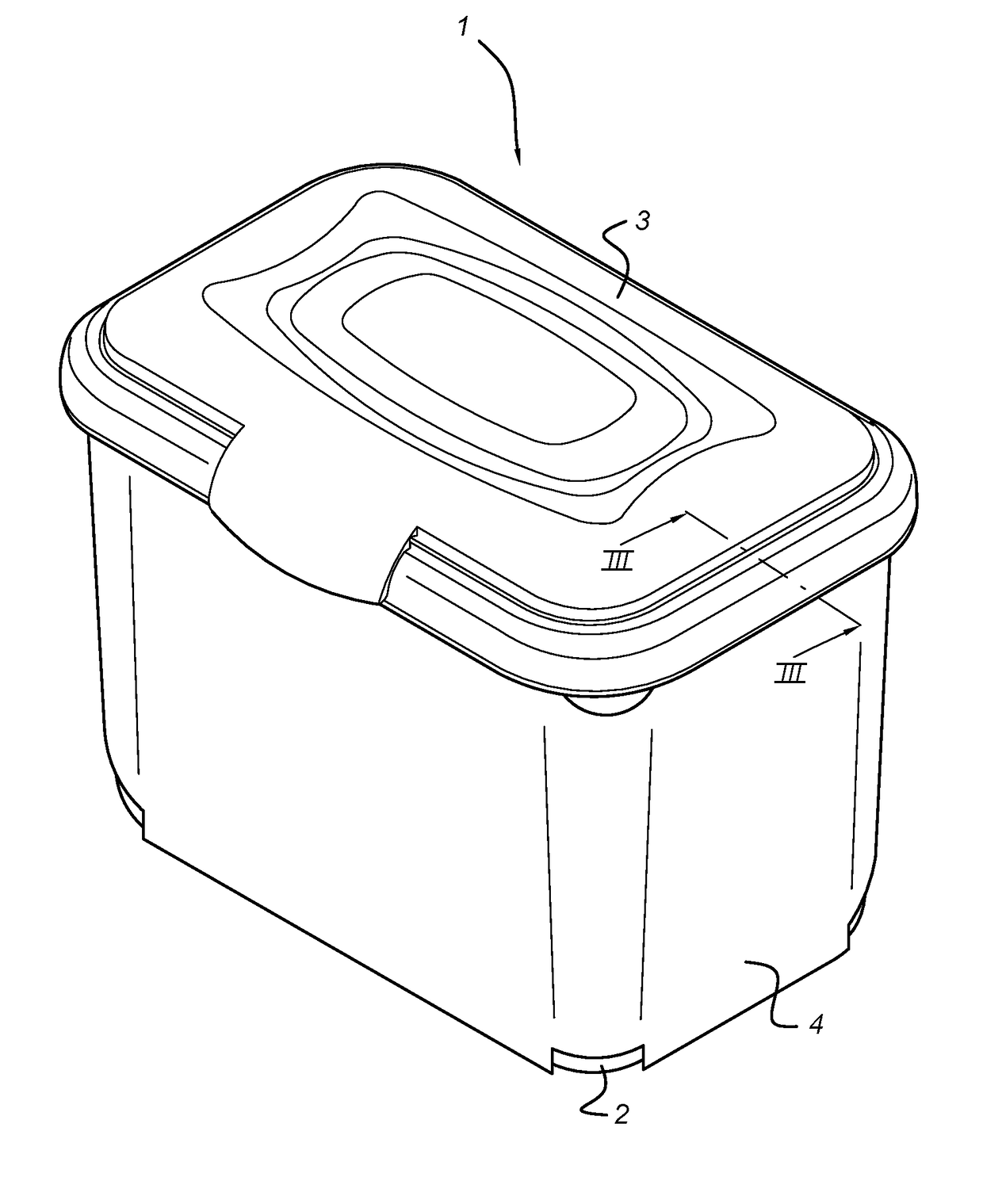
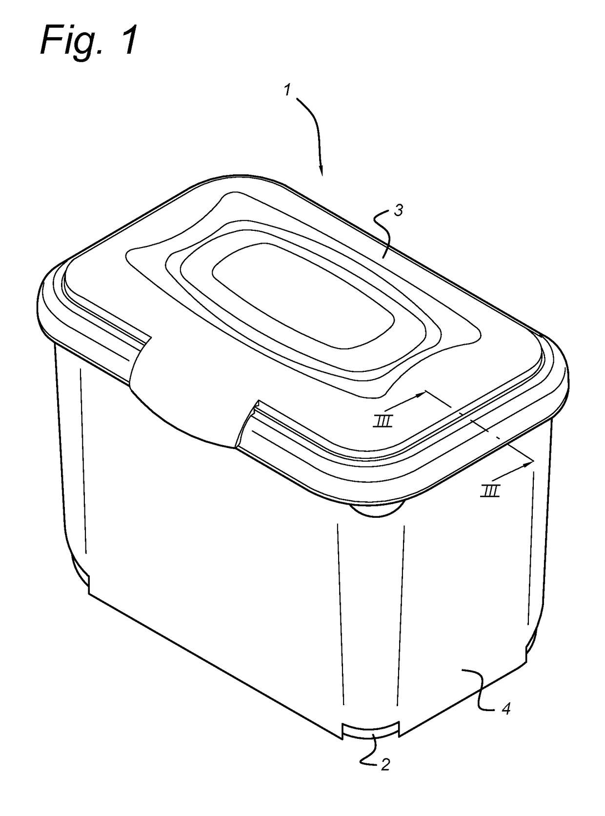
[0036]FIG. 1 shows in perspective view a package 1 incorporating the present invention. The package 1 is in its completed state and includes a tub 2, enclosed by a sleeve 4, and a lid assembly 3.

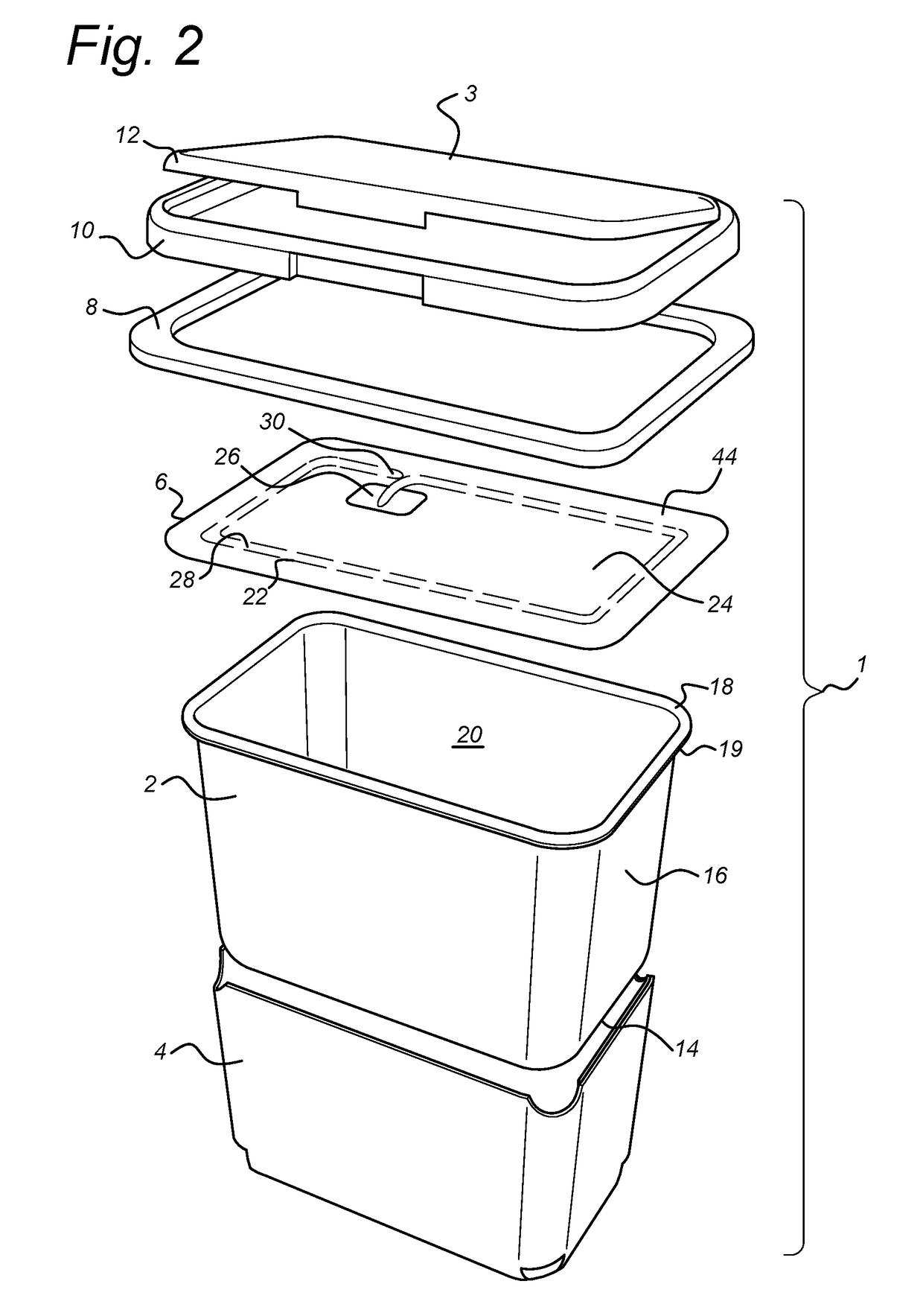
[0037]FIG. 2 shows a partially exploded view of the package 1 showing in further detail the component parts of the package 1, including the tub 2, the sleeve 4, a foil 6, a lower rim 8, an upper rim 10 and a lid 12. The tub 2 is thermoformed of a laminate of inner and outer relatively thin polypropylene material layers and an intermediate EVOH barrier layer. It includes a base 14 and a peripheral wall 16 defining a product containing space 20. The peripheral wall 16 extends to an upper edge 18 having an outwardly directed flange 19. The sleeve 4 is formed of carton.

[0038]Lower rim 8 is formed as a flat annular ring of a similar dimension to the outwardly directed flange 19. The lower rim 8 is injection moulded of polypropylene, although it will be understood that other appropriate materials ...


PUM

PropertyMeasurementUnit
areaaaaaaaaaaa
areaaaaaaaaaaa
anglesaaaaaaaaaa

Abstract

A tearable foil for closing a package comprises a plurality of layers laminated together, including at least an oxygen barrier layer and a cover layer. A tear line penetrates at least partially through the cover layer to define a tear strip extending from a pull tab to a tail, wherein the pull tab comprises lateral wings that are delaminated with respect to the remainder of the foil, on either side of a central region that is laminated to the remainder of the foil. A user may fold the lateral wings together at right angles to a plane of the foil and grip them to exert a force on the central region and thus commence tearing of the tear strip.

Description

BACKGROUND OF THE INVENTION1. Field of the Invention[0001]The present invention relates to sealing foils for use in packaging and in particular to single web sealing foils having a weakened tear line along which the foil may be torn to open the package. The invention also relates to a package and a method of forming such a sealing foil.2. Description of the Related Art[0002]Packages are available in many forms and sizes according to the product to be contained. In the food packaging industries, tub-like containers are frequently used for receiving a product that is dispensed from the tub during a period of use. The presence of a sealing foil can be of great importance in maintaining a product in sterile or fresh condition prior to first use. One form of foil that has been disclosed for such packaging is shown in WO2014062119. The foil comprises two layers or webs, welded together during a production stage, wherein the first layer is an aluminium laminate that can be heat sealed or o...

Claims


Application Information

Patent Timeline
Patent Type & Authority Applications(United States)
IPC IPC(8): B65D77/20B32B15/085B32B15/20B32B27/08B32B27/32B32B3/26
CPCB65D77/206B32B15/085B32B15/20B32B27/08B32B27/32B32B3/266B32B2307/31B32B2307/582B32B2307/7244B65D2251/0021B32B2439/70B65D2577/205B65D2577/2091B32B15/08B65D2251/0093B32B7/12B32B27/306B32B2250/04B32B2250/246B32B2307/514B32B2307/71B32B2307/732B32B2307/748B32B7/05B65D77/20
Inventor ARTS, JOSBUNCE, MARTIN CHRISTOPHER
Owner NV NUTRICIA
Why Eureka
Try Eureka