Femoral removal vena cava filter

a filter and vena cava technology, applied in the field of medical devices, can solve the problems of thrombosis risk, pulmonary embolism risk, and risk of downstream embolism or embolization of thrombi, and achieve the effect of reducing the risk of pulmonary embolism, and reducing the risk of thrombosis

Active Publication Date: 2013-04-25
COOK MEDICAL TECH LLC
View PDF37 Cites 5 Cited by
  • Summary
  • Abstract
  • Description
  • Claims
  • Application Information

AI Technical Summary

Benefits of technology

[0008]In another embodiment, the present invention provides a method for retrieving an intravascular filter from a patient's vena cava through the patient's femoral vein. The method involves percutaneously inserting a retrieval assembly into the patient's vasculature through the patient's femoral vein. The retrieval assembly includes a retrieval sheath, a first control member, and a second control member. In a second step, the method involves advancing the retrieval assembly through the patient's vasculature to a retrieval position proximal to an intravascular filter constructed in accordance with the present invention in the patient's vena cava. In a third step, the method involves contacting the shaft with the first control member to stabilize the intravascular filter. In a fourth step, the method involves attaching the second control member to the first cuff. In a fifth step, the method involves retracting the second control member proximally to move the first cuff in the second direction along the shaft such that the second cuff slides over the filtering portions of the struts to collapse the intravascular filter. In a sixth step, the method involves advancing the retrieval sheath distally over the intravascular filter. In a seventh step, the method involves removing the retrieval assembly and the intravascular filter from the patient's vasculature.

Problems solved by technology

Patients having such medical conditions face an increased risk of thrombosis in the peripheral vasculature, wherein thrombi break away from the vessel wall, risking downstream embolism or embolization.
For example, depending on the size, such thrombi pose a serious risk of pulmonary embolism wherein blood clots migrate from the peripheral vasculature through the heart and into the lungs.
It has been a challenge to design a vena cava filter suitable for removal through a patient's femoral vein.

Method used


Image

  • Femoral removal vena cava filter
  • Femoral removal vena cava filter
  • Femoral removal vena cava filter

Examples


Embodiment Construction

[0023]The present invention generally provides an intravascular filter suitable for deployment in a patient's vena cava and retrieval via the patient's jugular or femoral vein. The invention also provides a method for retrieving the intravascular filter from the patient's vena cava through the patient's femoral vein.

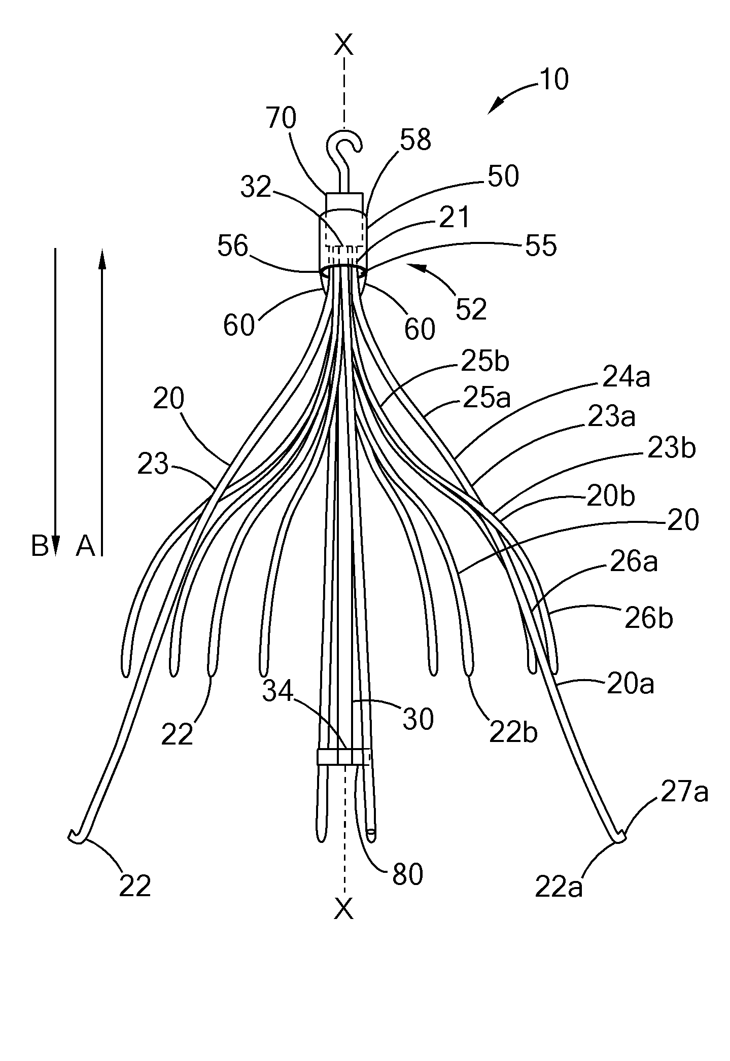
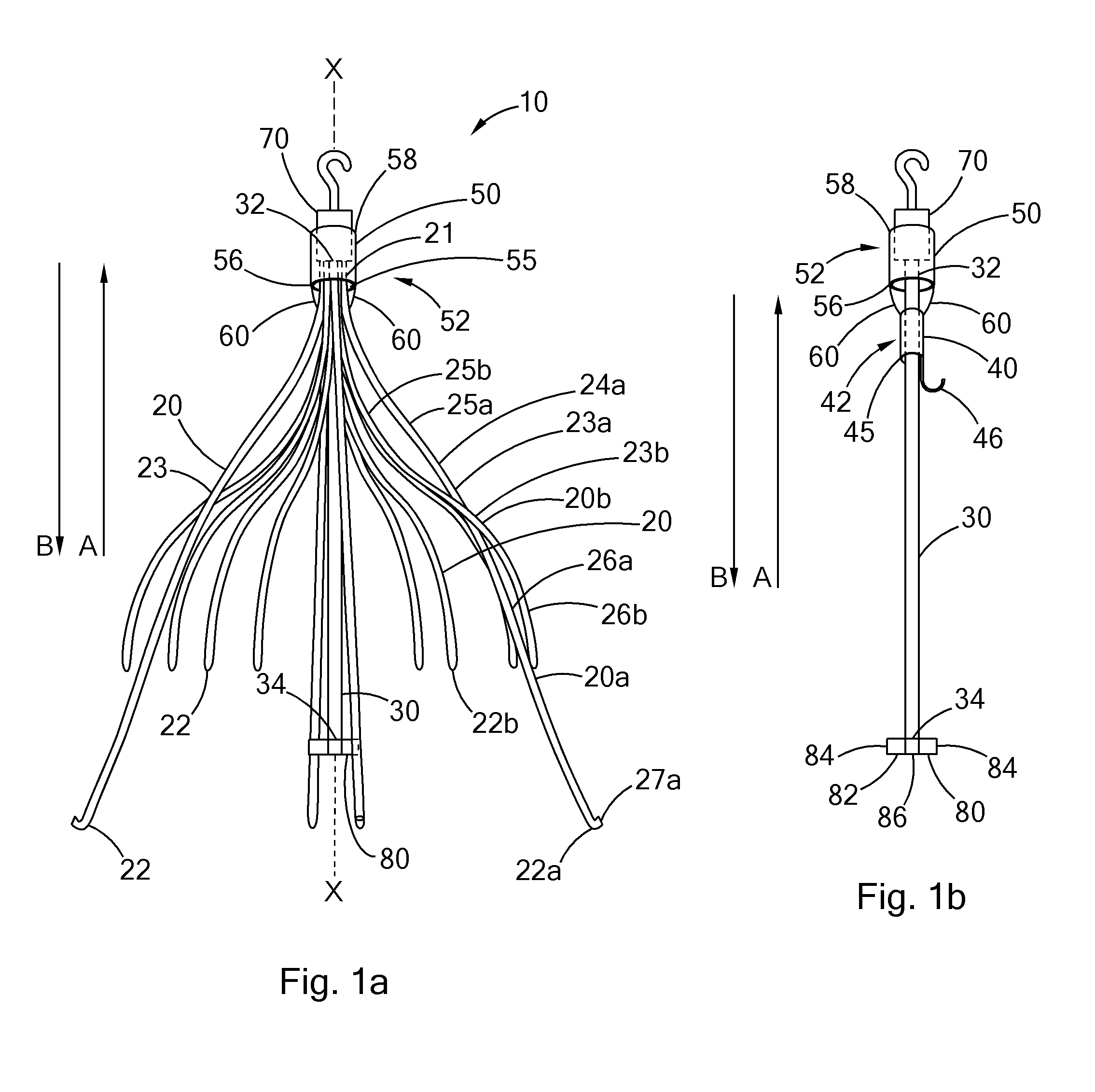
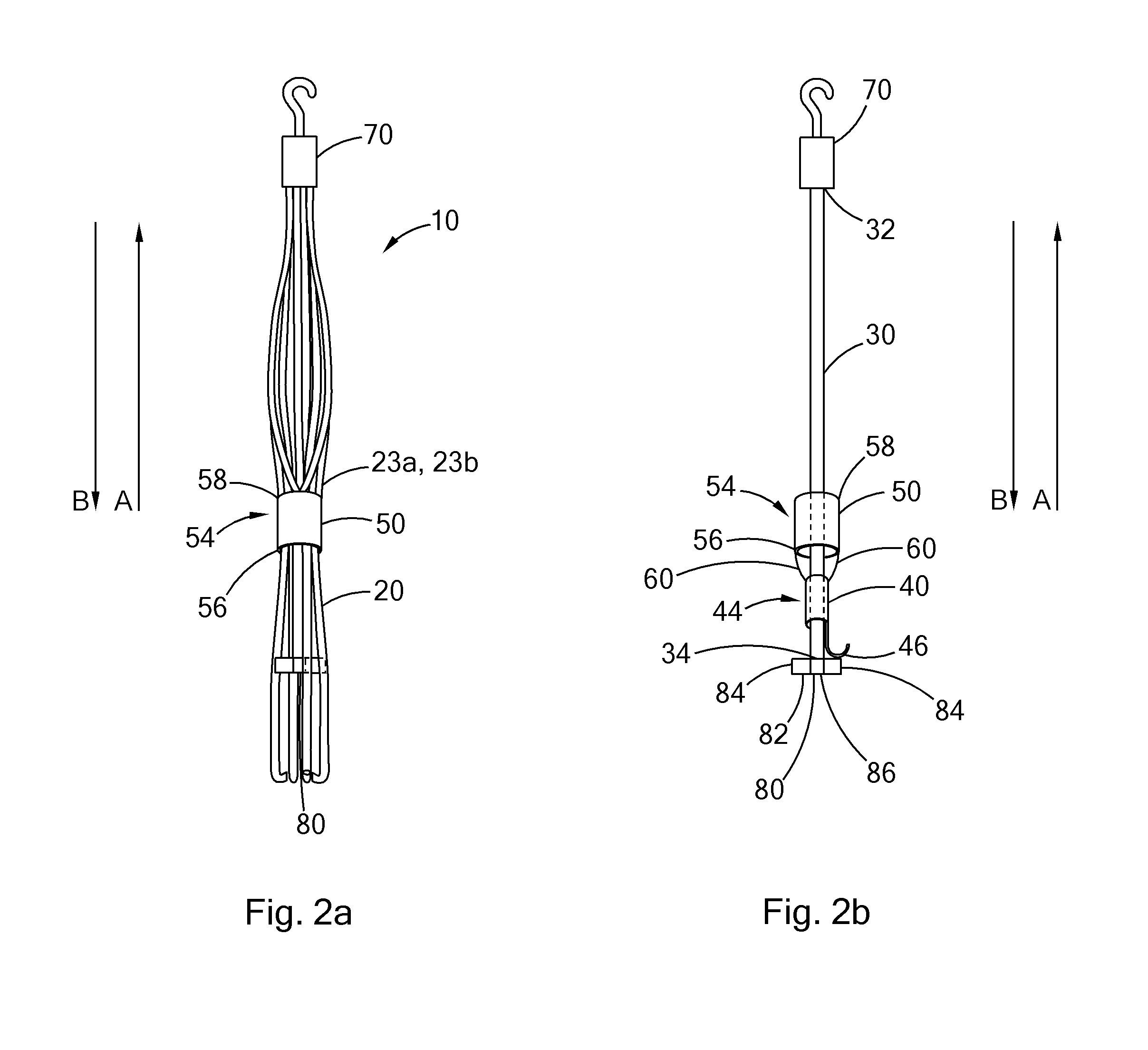
[0024]FIGS. 1a-b and 2a-b illustrate an intravascular filter 10 in accordance with the principles of the present invention. The filter 10 has an expanded state (FIG. 1a) for capturing thrombi in a patient's blood vessel (e.g., in the patient's vena cava) and a collapsed state (FIG. 2a) for removal from the patient's vasculature.

[0025]The filter 10 comprises a plurality of struts 20, a shaft 30, a first cuff 40 disposed on the shaft 30, and a second cuff 50 disposed over the struts 20 and connected to the first cuff 40. For the sake of clarity, certain elements of the filter 10 have been omitted from FIGS. 1a-b and 2a-b. More specifically, the first cuff 40 has been omitt...


PUM


Abstract

An intravascular filter configured for retrieval through a patient's femoral vein and a method for retrieving the filter through the patient's femoral vein. The filter includes a plurality of struts having connected ends attached together along a longitudinal axis, a shaft disposed along the longitudinal axis and having a first end disposed with the connected ends of the struts, a first cuff slidably disposed on the shaft, and a second cuff disposed over the struts and connected to the first cuff.

Description

BACKGROUND[0001]The present invention relates to medical devices. More particularly, the invention relates to a removable intravascular filter that can be removed from the vena cava of a patient through the patient's jugular or femoral vein.[0002]Filtering devices that are percutaneously placed in the vena cava have been available for a number of years. A need for such filtering devices arises in trauma patients, orthopedic surgery patients, neurosurgery patients, or in patients having medical conditions requiring bed rest or non-movement. Patients having such medical conditions face an increased risk of thrombosis in the peripheral vasculature, wherein thrombi break away from the vessel wall, risking downstream embolism or embolization. For example, depending on the size, such thrombi pose a serious risk of pulmonary embolism wherein blood clots migrate from the peripheral vasculature through the heart and into the lungs.[0003]Historically, vena cava filters were considered to be p...

Claims


Application Information

Patent Timeline
Patent Type & Authority Applications(United States)
IPC IPC(8): A61F2/01
CPCA61F2/01A61F2002/011A61F2230/008A61F2230/005A61F2230/0067A61F2002/016A61F2/011A61F2/0105
Inventor HONEYCUTT, JUSTIN
Owner COOK MEDICAL TECH LLC
Why Eureka
Try Eureka