Battery Temperature Control Device

a lithium ion battery and temperature control technology, which is applied in the field of battery temperature control devices, can solve the problems of increasing battery power consumption, reducing the range of electric vehicles, and affecting the service life of secondary cells, so as to prevent deterioration, suppress battery power consumption, and improve the range of vehicles

Inactive Publication Date: 2013-04-25
HITACHI AUTOMOTIVE SYST LTD
View PDF11 Cites 30 Cited by
  • Summary
  • Abstract
  • Description
  • Claims
  • Application Information

AI Technical Summary

Benefits of technology

[0012]That is, when setting a substantially median value of the recommended temperature range (for example, 20° C.) as the target battery temperature in different environments as shown in FIGS. 11A to 11C, the amount of heat emitted to the outside from a battery increases as the ambient temperature decreases from near the ordinary temperature (10° C.), and the amount of power used by a heater or the like to maintain the battery temperature at the target battery temperature (20° C.) is thereby increased. As a result, the battery power that is consumed increases as the ambient temperature falls, relatively decreasing the power for driving the motor of the electric vehicle, and the range of the electric vehicle is thereby drastically reduced.
[0014]According to the battery temperature adjusting devices disclosed in JP Patent Publication (Kokai) No. 10-252467 A (1998) and JP Patent Publication (Kokai) No. 2009-110829 A, heat energy use efficiency for controlling the battery temperature can be improved by introducing the air inside the vehicle cabin into the battery.
[0016]The present invention has been made from the standpoint of the above-described problems, and its aim is to provide a battery temperature control device capable of maintaining both the range of a vehicle and a battery life at a high level.
[0018]According to the battery temperature control device of the present invention, with the battery temperature control for an electric vehicle including, for example, a lithium ion battery, while the battery can be prevented from deteriorating by basically setting the target battery temperature used for controlling the battery temperature at near the center of the recommended temperature range, in the case that the energy (the power) necessary for controlling the battery temperature is assumed to greatly affect the range of the vehicle, the energy (the power) necessary for controlling the battery temperature is kept at minimum, the power consumption of the battery is suppressed, and the range of the vehicle can thereby be maintained.

Problems solved by technology

However, in the case that the ambient temperature is extremely low or extremely high, the energy (the power) necessary to control the battery temperature is very high, and there is an issue that the range of the electric vehicle is drastically reduced.
As a result, the battery power that is consumed increases as the ambient temperature falls, relatively decreasing the power for driving the motor of the electric vehicle, and the range of the electric vehicle is thereby drastically reduced.

Method used


Image

  • Battery Temperature Control Device
  • Battery Temperature Control Device
  • Battery Temperature Control Device

Examples


first embodiment

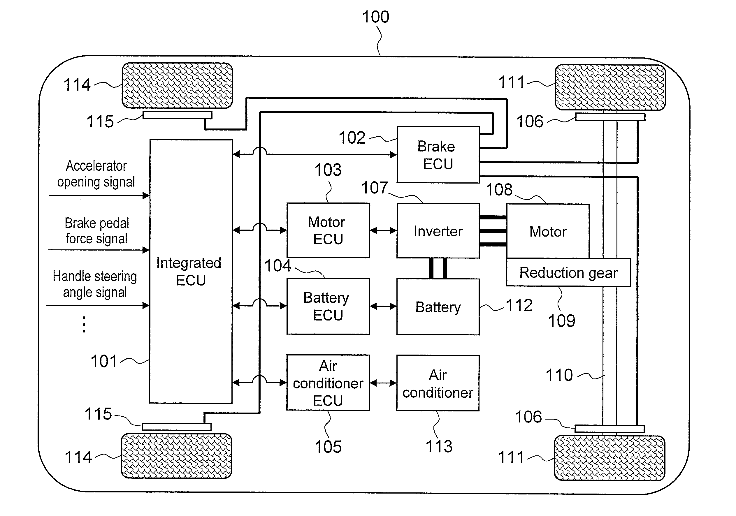
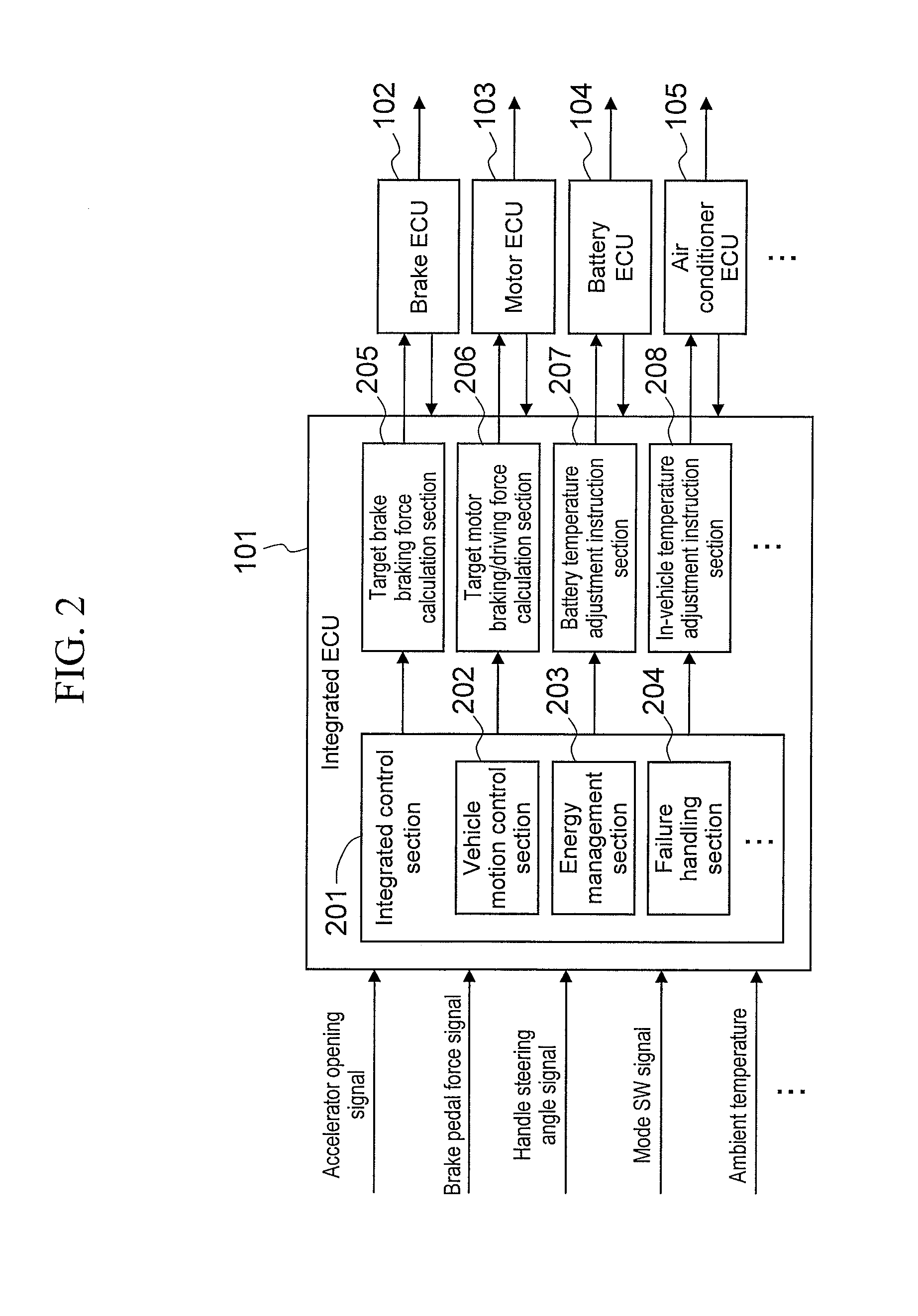
[0032]FIG. 1 schematically shows the system configuration of an electric vehicle 100 to which a first embodiment of the battery temperature control device according to the present invention is applied.

[0033]The electric vehicle 100 includes a battery (a lithium ion battery) 112, an inverter 107 for performing power conversion on the battery 112, and a motor 108 that is driven by the power of the inverter 107, and motor driving force generated by the driving of the motor 108 is transmitted to drive wheels (front wheels) 111 via a reduction gear 109 and an axle (a drive shaft) 110, enabling a desired travelling state to be achieved. Also, brake discs 106 and 115 are provided respectively to the front wheels 111 and rear wheels 114 of the electric vehicle 100, and the turning of the front wheels 111 and the rear wheels 114 can be controlled according to an operation or the like of a user. The electric vehicle 100 further includes an air conditioner 113, and is capable of realizing suit...

second embodiment

[0064]FIG. 7 schematically shows a second embodiment of the battery temperature control device. Additionally, a battery temperature control device 600 of the second embodiment differs from the battery temperature control device 500 of the first embodiment in that the target battery temperature calculation section 301 is simplified by fixing the target battery temperature of the target battery temperature calculation section 301 to the recommended temperature range median value (for example, 20° C.), and in that a power supply limiter for battery temperature control 303 is provided after the PID feedback controller 302 of the battery temperature control section 210, and other structural elements are the same of those of the battery temperature control device 500 of the first embodiment. Accordingly, the structural elements same as those of the battery temperature control device 500 of the first embodiment are denoted with the same symbols and detailed description thereof is omitted.

[...


PUM

PropertyMeasurementUnit
temperaturesaaaaaaaaaa

Abstract

A battery temperature control device for an electric vehicle is provided which is capable of maintaining both the range of the electric vehicle and the battery life at a high level without drastically reducing either of them. A recommended temperature range suitable for battery use and a usable temperature range in which a battery is usable and which is wider than the recommended temperature range are included, and while the battery temperature is basically controlled to converge to the recommended temperature range to maintain the battery life, in a situation where the power consumption necessary for controlling the battery temperature to converge to the recommended temperature is increased, making it difficult to travel a desired travelling distance, the recommended temperature range is switched to the usable temperature range and the battery temperature is controlled to converge to the usable temperature range, and the power consumption necessary for controlling the battery temperature is suppressed and the range of the vehicle is maintained.

Description

BACKGROUND OF THE INVENTION[0001]1. Field of the Invention[0002]The present invention relates to a battery temperature control device, and more particularly, to a battery temperature control device for a lithium ion battery used in an electric vehicle.[0003]2. Background Art[0004]In recent years, electric cars are gaining attention as environment-friendly vehicles. As batteries used in the electric cars, lithium ion batteries with high energy density and high charge acceptability are becoming the mainstream.[0005]Now, the lithium ion battery is highly dependent on temperature with respect to the charge / discharge performance and the life property, and to improve the battery performance such as the charge / discharge performance and the life property, the battery temperature has to be maintained within an appropriate temperature range.[0006]JP Patent Publication (Kokai) No. 10-252467 A (1998) and JP Patent Publication (Kokai) No. 2009-110829 A disclose conventional devices for adjusting...

Claims


Application Information

Patent Timeline
Patent Type & Authority Applications(United States)
IPC IPC(8): H01M10/42B60L11/18H01M10/60H01M10/613H01M10/615H01M10/625H01M10/633H01M10/635H01M10/6563H01M10/6571
CPCH01M10/486H01M2220/20Y02T10/7005H02J7/047Y02T10/7011B60L11/1872Y02T10/705B60L58/25Y02T10/70Y02E60/10H02J7/04H02J7/007192
Inventor SATO, SHINYAKOJIMA, TAKAOKOBAYASHI, HITOSHI
Owner HITACHI AUTOMOTIVE SYST LTD
Why Eureka
Try Eureka