Hydraulic Fracturing Method

a technology of hydraulic fracturing and fracture network, which is applied in the direction of fluid removal, chemistry apparatus and processes, borehole/well accessories, etc., can solve the problems that existing treatment techniques have not been sufficiently effective for forming fracture networks with high fracture densities

Inactive Publication Date: 2013-05-02
SCHLUMBERGER TECH CORP
View PDF10 Cites 36 Cited by
  • Summary
  • Abstract
  • Description
  • Claims
  • Application Information

AI Technical Summary

Benefits of technology

[0010]The total volume of the fluid injected in steps (c) preferably makes up less than 10 percent of the total volume of fluid injected in the treatment. In each cycle the ratio of the volume of fluid in stage C to the volume of fluid in stage B is preferably less than about 1 / 10.

Problems solved by technology

While slickwater fluids usually provide poor transport for conventional proppants, due to their very low viscosity, they still have been found effective and economic.
Existing treatment techniques have not proven to be sufficiently effective for formation of fracture networks with high fracture densities.

Method used


Image

  • Hydraulic Fracturing Method
  • Hydraulic Fracturing Method
  • Hydraulic Fracturing Method

Examples


example 1

[0037]A fluid slug prepared from a borate cross-linked guar gel, having a guar concentration of 6 g / L (50 lb / 1000 gal) was placed in a Plexiglas settling slot with dimensions 1000×300×4 mm, above a slug of similar-density slickwater containing 0.05 weight percent of a polyacrylamide friction reducer. No slug diffusion during the experimental time of 4 hours at room temperature was observed. The viscous slug remained consolidated and floated on the slickwater slug without settling.

example 2

[0038]The behavior of a viscous slug being transported in a long horizontal pipe was studied. A laminar fluid flow regime was tested. These data can be used to evaluate slug transport inside a fracture. In order to investigate slug transport dependencies, a special set-up was constructed. It consisted of a clear plastic water pipe (35 m in length and 18 mm ID), systems for injection of the viscous slug and of a base fluid, a water pump, and two photo sensors (one at the beginning and one at the end of the pipe) to determine the length of the viscous slug, and a data acquisition system. A special loop was used for injection of slugs of the viscous fluid. A viscous slug of a desired composition was loaded into the slug injection loop before the experiment and was isolated from the main line by valves. Base fluid was pumped through the pipe for several minutes until the base fluid flow stabilized. Once flow stabilization was attained, the flow was directed into the slug sample injectio...

example 3

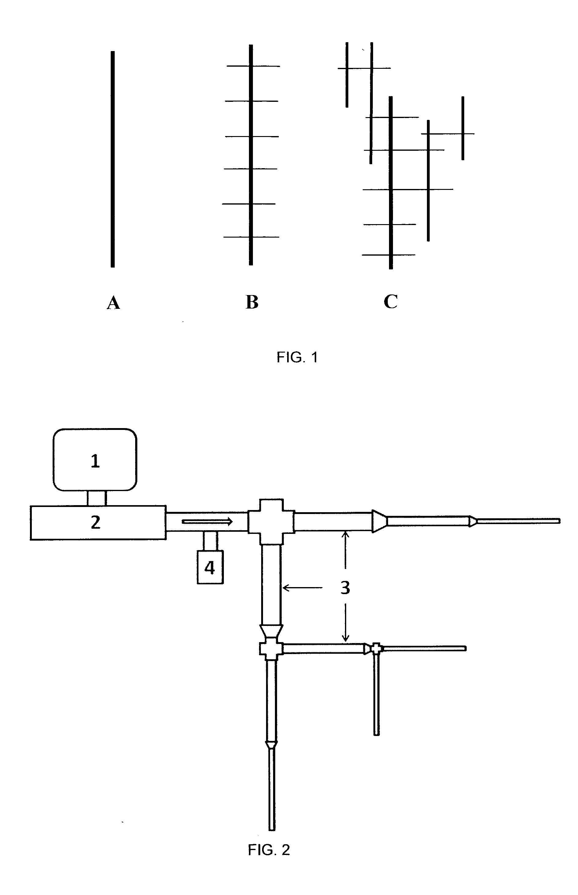
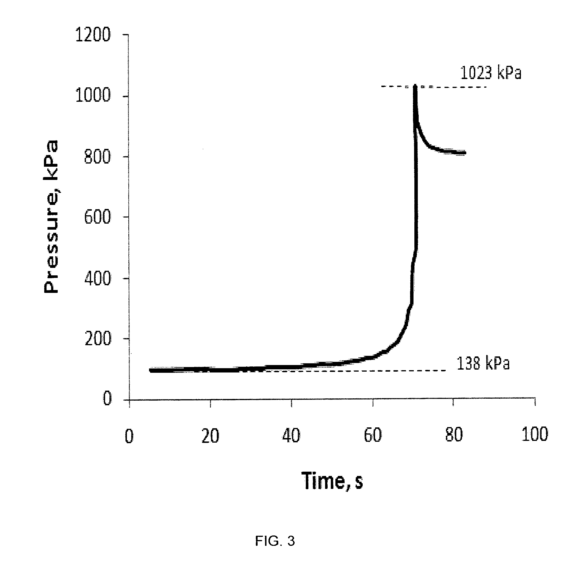
[0040]A manifold [3] as shown in FIG. 2 was built using Swagelok tubes with outer diameters varying from 6.35 mm (0.25 in) down to 1.59 mm ( 1 / 16 in). FIG. 3 shows the test results in which the pressure inside the tube was plotted against time. The same slickwater as used in Examples 1 and 2 was pumped through the manifold with a Knauer pump [1] at 0.5 l / min flow rate with pressures generally not exceeding 138 kPa (20 psi). Slugs of the crosslinked gel used in Examples 1 and 2 were then placed in the slurry tank [2] and the pressure was followed during pumping; the pressure increased up to 1007 kPa (146 psi), at which pressure the pressure relief rapture disk [4] broke. The manifold system emulates a complex fracture network during the diversion stage, and the rupture disk break mimics fracturing of a non-stimulated zone of the reservoir due to the net pressure increase.


PUM


Abstract

A method is given for diverting injected slickwater in a hydraulic fracturing treatment. The diversion fluid is preferably a substantially proppant free viscous fluid that causes a net pressure increase and plugging of some of the microfractures in the initial fracture system created, which induces formation of supplementary microfractures connected to the initial fracture network and in-creases the contact area with the formation rock. The method generates a greater fracture network complexity and thus a higher contact area with the reservoir during a single treatment cycle.

Description

BACKGROUND OF THE INVENTION[0001]Recovery of hydrocarbons from unconventional reservoirs, for example tight sandstones and shales, usually requires stimulation, for example hydraulic fracturing, to achieve economic production. Water or slickwater (so-called when water with a small amount of a friction reducer is used) are often used as fracturing fluids for stimulation of low permeability unconventional reservoirs. Such treatments are designed to stimulate large reservoir volumes and to open more surface area of hydrocarbon-retaining rock, thus enhancing production. While slickwater fluids usually provide poor transport for conventional proppants, due to their very low viscosity, they still have been found effective and economic. Using low-viscosity fluids for fracture stimulation in low-permeability reservoirs sometimes results in the creation of a network of intersecting fractures and sometimes results in propagation of a single fracture plane. Although the low conductivity achiev...

Claims


Application Information

Patent Timeline
Patent Type & Authority Applications(United States)
IPC IPC(8): E21B43/267
CPCC09K8/685E21B43/267C09K8/80
Inventor BARMATOV, EVGENY BORISOVICHMAKARYCHEV-MIKHAILOV, SERGEY MIKHAILOVICHPOTAPENKO, DMITRIY IVANOVICHFREDD, CHRISTOPHER N.
Owner SCHLUMBERGER TECH CORP
Why Eureka
Try Eureka