Vacuum deposition method for forming gradient patterns using vacuum device

a vacuum device and gradient pattern technology, applied in the field of vacuum deposition method, to achieve the effect of low installation

Inactive Publication Date: 2013-05-02
KIM SANG YEONG
View PDF4 Cites 6 Cited by
  • Summary
  • Abstract
  • Description
  • Claims
  • Application Information

AI Technical Summary

Benefits of technology

[0006]Accordingly, the present invention has been made to solve the above-mentioned problems occurring in the prior arts, and it is an object of the present invention to provide a vacuum deposition method for forming gradient patterns using a vacuum device, which can break the monotony of the conventional solid-color deposition and provide an artistic and esthetic sense to thereby produce high-quality products with fresh and beautiful colors, and which is low in additional installation fee because blocking members for forming gradient patterns are additionally mounted to the conventional vacuum deposition device.

Problems solved by technology

Such a conventional vacuum deposition method is environmental-friendly and has been recognized as a superior method to protect products, but because it is deposition of a solid color, it remains a problem to supplement its default in an aspect of design.

Method used


Image

  • Vacuum deposition method for forming gradient patterns using vacuum device
  • Vacuum deposition method for forming gradient patterns using vacuum device
  • Vacuum deposition method for forming gradient patterns using vacuum device

Examples


embodiment 1

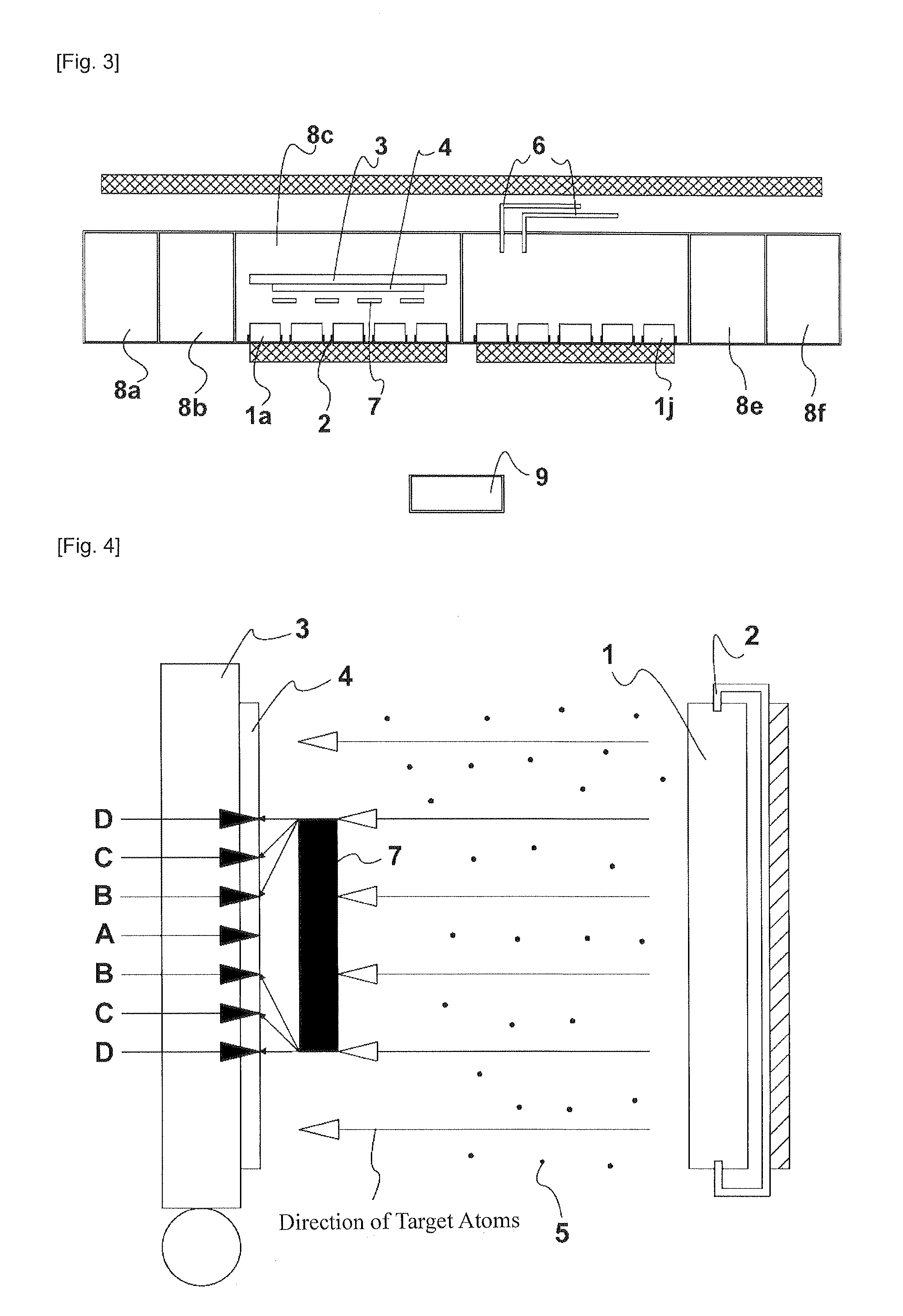
[0039]Titanium was used as the metal targets 1, and the degree of vacuum inside the chambers 8 was 8.5K×10−4 TORR and argon gas of 450 SCCM was injected by two DC sputters of 5 kw. After that, as shown in FIG. 5, the plural (seven) blocking members 7 were vertically arranged at a predetermined interval between the substrate 4 and the metal targets 1, and then, plasma was irradiated, and thereby, vertically gradient patterns were produced as shown in FIG. 6.

[0040]In FIG. 6, black parts are parts which were not affected by the blocking members 7, but white parts are parts which had a relatively great influence by the blocking members.

embodiment 2

[0041]Titanium was used as the metal targets 1, and the degree of vacuum inside the chambers 8 was 8.5K×10−4 TORR and argon gas of 450 SCCM was injected by two DC sputters of 5 kw. After that, as shown in FIG. 7, the plural (two) blocking members 7 were horizontally arranged at a predetermined interval between the substrate 4 and the metal targets 1, and then, plasma was irradiated, and thereby, the deposited form was indicated as shown in FIG. 6.

[0042]In FIG. 8, black parts are parts which were not affected by the blocking members 7, but white parts are parts which had a relatively great influence by the blocking members.

[0043]FIG. 9 is a view showing another example of the blocking members according to the present invention, and FIG. 10 is a view showing a gradient pattern formed by the blocking members of FIG. 9.

[0044]If blocking members 7, each of which includes a circular body 7b and projections 7a formed on right and left sides or upper and lower sides of the circular body 7b ...


PUM

PropertyMeasurementUnit
voltageaaaaaaaaaa
transmissionaaaaaaaaaa
transmission ratesaaaaaaaaaa

Abstract

Disclosed therein is a vacuum deposition method for forming gradient patterns using a vacuum device. The vacuum device comprises vacuum chambers (8) containing a substrate (4) and metal targets (1) therein and a blocking member (7) interposed between the substrate (4) and the metal targets (1). When voltage is applied to the metal targets (1), atoms (5) popping out from the metal targets (1) are deposited onto the substrate (4) in such a way that the amount of atoms deposited on the substrate (4) is gradually decreased from the edge toward the center of the blocking member (7) due to interruption of the blocking member (7).

Description

BACKGROUND OF THE INVENTION[0001]1. Field of the Invention[0002]The present invention relates to a vacuum deposition method for carrying out vacuum deposition onto the surface of a product using a vacuum device, which additionally includes a plurality of blocking members to provide various patterns according to their arranged conditions, and more particularly, to a vacuum deposition method for forming gradient patterns using a vacuum device that forms a gradient-patterned film on a substrate located at the back of the blocking members by depositing atoms of metal targets on the substrate.[0003]2. Background Art[0004]In general, vacuum deposition is a method to apply negative voltage to metal targets by a vacuum device, which includes vacuum chambers, a substrate, and the metal targets. When the negative voltage is applied to the metal targets, argon is ionized by electrons emitted from the cathode and becomes argon plasma, and positive argon ions in the argon plasma are accelerated ...

Claims


Application Information

Patent Timeline
Patent Type & Authority Applications(United States)
IPC IPC(8): C23C14/34
CPCC23C14/044C23C14/14C23C14/024H01J37/3426H01J37/3447C23C14/34
Inventor KIM, SANG YEONG
Owner KIM SANG YEONG
Why Eureka
Try Eureka