Eureka AIR delivers breakthrough ideas for toughest innovation challenges, trusted by R&D personnel around the world.

Structural articulation joint for high density mobile carriage

a structure articulation and carriage technology, applied in the direction of dismountable cabinets, couplings, manufacturing tools, etc., can solve the problems of increasing the amount of floor space used for product storage, not being able to use product storage, and not being able to provide a level surface for the rails along which the racks mov

Active Publication Date: 2013-05-02
SPACESAVER
View PDF55 Cites 35 Cited by
  • Summary
  • Abstract
  • Description
  • Claims
  • Application Information

AI Technical Summary

Benefits of technology

The patent is about a mobile rack system that can be used in areas with seismic activity. The system includes couplers between adjacent racks that allow them to move relative to each other. Each coupler is made up of a coupling bracket, a receiving bracket, and a movement bracket. The couplers create a strong connection between the racks, making them act as a single unit for stability evaluation. The couplers allow for relative movement between the racks while still providing stability.

Problems solved by technology

Moreover, since each aisle is typically as wide, if not wider than, the rack itself, more than half the floor space occupied by the industrial rack system may be occupied by aisles and thus not usable for product storage.
Mobile industrial rack systems, however, are designed to reduce the number of fixed aisles and, as a result, increase the amount of floor space used for product storage.
In both instances, measures must be taken to provide a level surface for the rails along which the racks move, which are generally quite costly.

Method used


Image

  • Structural articulation joint for high density mobile carriage
  • Structural articulation joint for high density mobile carriage
  • Structural articulation joint for high density mobile carriage

Examples


Embodiment Construction

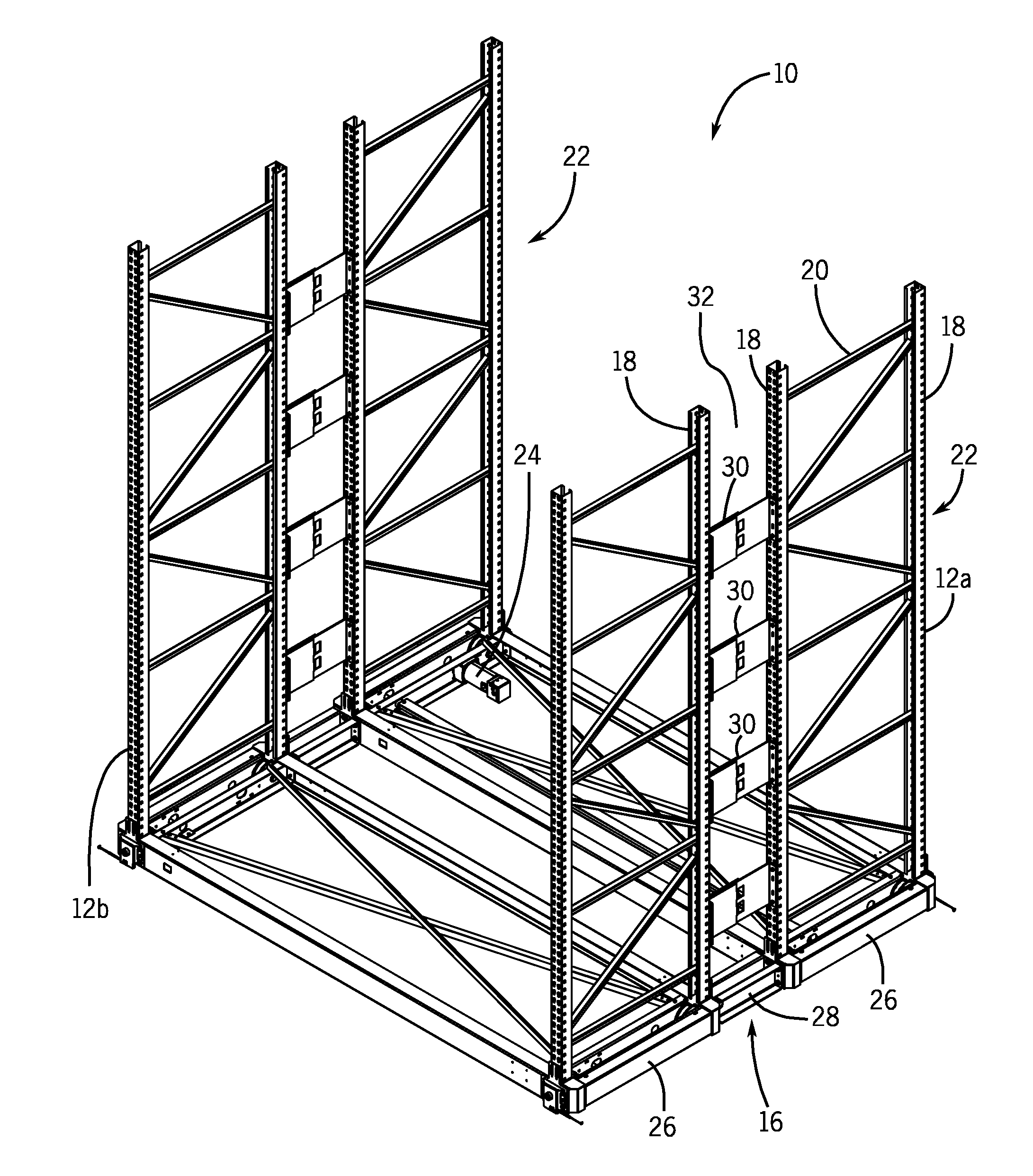
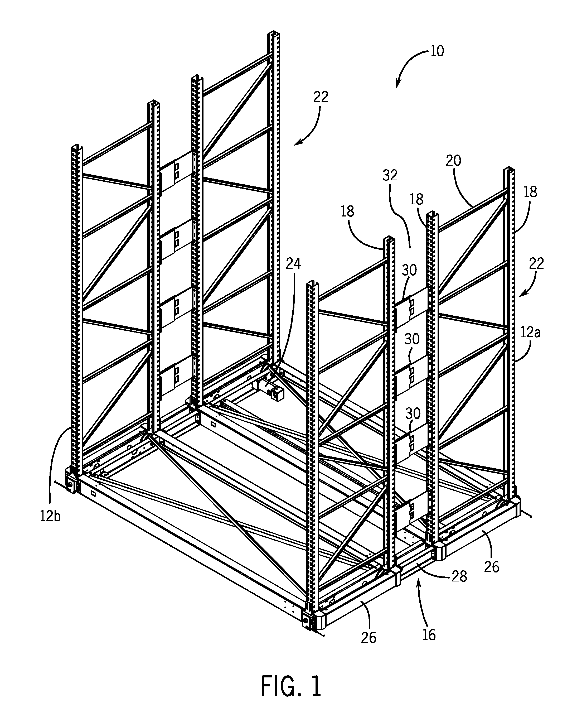
[0021]FIG. 1 illustrates a mobile industrial rack system 10 that includes a series of industrial storage racks 12 that are movable along a series of spaced and parallel rails (not shown) that are mounted within the floor of a building. In the embodiment shown, the industrial storage racks 12 are arranged in pairs so as to form multiple multi-rack units 16, with each multi-rack unit 16 having a forward rack 12a and a rearward rack 12b, wherein the multi-rack unit 16 is movable as a single unit. Each multi-rack unit 16 is associated with a control interface that controls movement of the industrial storage racks 12 along the rails mounted to the building floor.

[0022]As illustrated in FIG. 1, each end of the individual racks 12 includes a pair of vertical uprights 18 that are joined to each other by a series of braces 20. The series of braces 20 and uprights 18 create a relatively rigid end frame 22 for each of the racks 12. Although not illustrated in FIG. 1, shelving is positioned bet...


PUM


Abstract

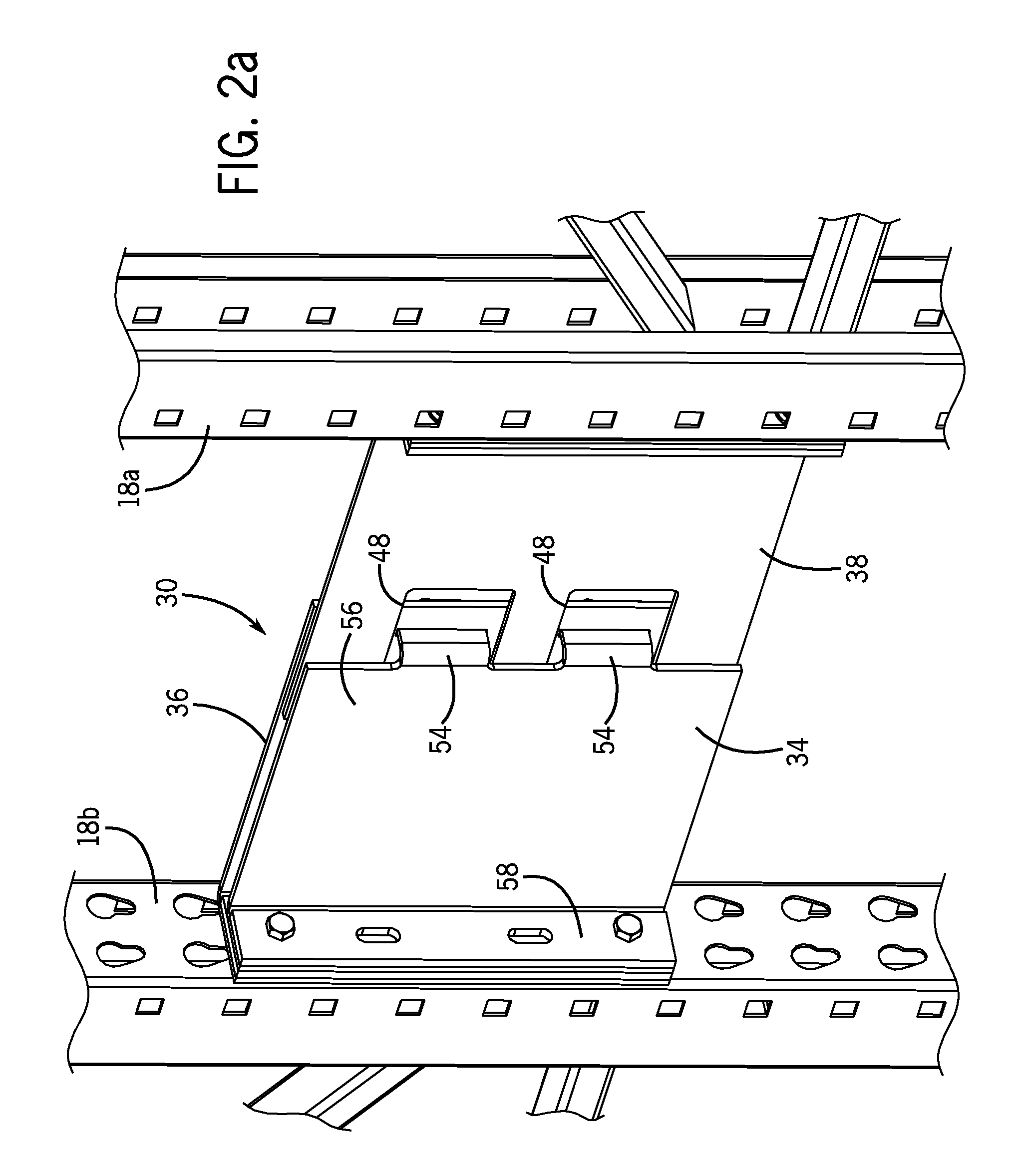
A structural coupler for joining two storage racks of a mobile rack system. The coupler includes three separate components that are movable relative to each other to allow for relative movement between adjacent storage racks while providing the structural stability to prevent tipping of the storage racks. The coupler includes a coupling bracket that includes a pair of tabs that extend through open slots formed in a movement bracket and through receiving slots formed in a receiving bracket. A removable connector prevents separation of the coupler in the assembled condition while the size of the coupling tabs relative to the open slots allows the three components to move relative to each other. A series of individual couplers can be used along the height of the uprights that form part of each of the individual storage racks.

Description

CROSS-REFERENCE TO RELATED APPLICATION[0001]The present application is based on and claims priority to U.S. Provisional Patent Application Ser. No. 61 / 552,697 filed Oct. 28, 2011.BACKGROUND OF THE INVENTION[0002]The present disclosure generally relates to industrial storage systems and, more particularly, to a mobile industrial rack system for use in areas having seismic activity or on unleveled flooring.[0003]Industrial rack systems are commonly used in storage facilities to store products until those products are shipped either directly to a consumer or to a retailer. Typically, the industrial racks store loaded pallets that are placed on and removed from the racks using a forklift. The industrial racks are spaced from one another in a manner to form relatively wide aisles to allow sufficient room for the forklift to load and remove the pallets. Since each industrial rack has a fixed position, each industrial rack must have a dedicated aisle. Moreover, since each aisle is typicall...

Claims


Application Information

Patent Timeline
Patent Type & Authority Applications(United States)
IPC IPC(8): A47B55/00F16B12/44
CPCA47B55/00F16B12/44A47B53/00Y10T403/70B65G1/10B65G1/02B62B1/10
Inventor YANIAK, DAVID JOSEPHMUTH, JAMES C.
Owner SPACESAVER
Why Eureka
Eureka Blog
Learn More