Integrated photovoltaic panel with sectional maximum power point tracking

a photovoltaic panel and integrated technology, applied in the direction of d ac network circuit arrangement, semiconductor devices, etc., can solve the problems of insufficient power supply of pv panels, insufficient power supply of pv cells, etc., to achieve the effect of optimizing power transfer

Active Publication Date: 2013-05-02
VOLTERRA SEMICONDUCTOR
View PDF27 Cites 35 Cited by
  • Summary
  • Abstract
  • Description
  • Claims
  • Application Information

AI Technical Summary

Benefits of technology

[0009]An integrated photovoltaic panel has an integral DC-DC converter circuit with inputs adapted for coupling to at least one photovoltaic device, a first switching device, a first and second output, and a freewheel device. The converter also has a control unit adapted to control switching of the first switching device. The PV panel has a transparent substrate to which PV devices are mounted, at least one PV device feeds the DC-DC converter. A laminating material seals the first PV device and the first converter circuit to the transparent substrate. In other embodiments, the panel has multiple DC-DC converter circuits connected with outputs in series, each converter circuit connected to separate PV devices. In some embodiments the DC-DC converters are complete with inductors, in other embodiments a common output inductance is shared by multiple DC-DC converters of the panel, in a particular embodiment the common output inductance is parasitic inductance of the panel.
[0010]An integrated photovoltaic panel has an integral DC-DC converter circuit with inputs adapted for coupling to at least one photovoltaic device, a first switching device, a first and second output, and a freewheel device. The converter also has a control unit adapted to control switching of the first switching device. The PV panel has a transparent substrate to which PV devices are mounted, at least one PV device feeds the DC-DC converter. A laminating material seals the first PV device and the first converter circuit to the substrate.
[0011]An alternative integrated PV panel has a transparent substrate, and several sections of PV devices and electronics bonded to the substrate. Each section has multiple PV devices, each PV device with at least one PV cell, the PV devices of each section are electrically coupled in series to an electric circuit carrier, such as a printed circuit board (PCB) assembly having terminals for connection to the PV devices and embodying a converter circuit. The converter circuit embodied on or in the electric circuit carrier has at least a first switching device, a freewheel device, and a control unit adapted to control switching of the first switching device to optimize power transfer to the converter circuit from PV devices. Outputs of the converter circuits are outputs of the sections and are electrically connected in series and to panel terminals.

Problems solved by technology

PV panels often, however, provide less output power than expected from known device efficiency and illumination.
This happens in part because typical panels are temperature sensitive, they must have sufficient cells connected in series to provide battery charging voltage at high temperatures, this cell count becomes excessive at low temperatures where PV cells produce their best output voltage.
Other losses occur when any one series-connected PV cell in a panel generates less current than other cells in the panel—barring additional circuitry, the output current of a series string of PV cells is effectively limited by photocurrent produced in the weakest, or most shaded, cell.
Since shading affects photocurrent produced in cells, often limiting current production of a series string of cells to that of a most-shaded cell of the string, un-shaded cells in the same series strings may yield substantially less power than they are otherwise capable of.

Method used


Image

  • Integrated photovoltaic panel with sectional maximum power point tracking
  • Integrated photovoltaic panel with sectional maximum power point tracking
  • Integrated photovoltaic panel with sectional maximum power point tracking

Examples


Embodiment Construction

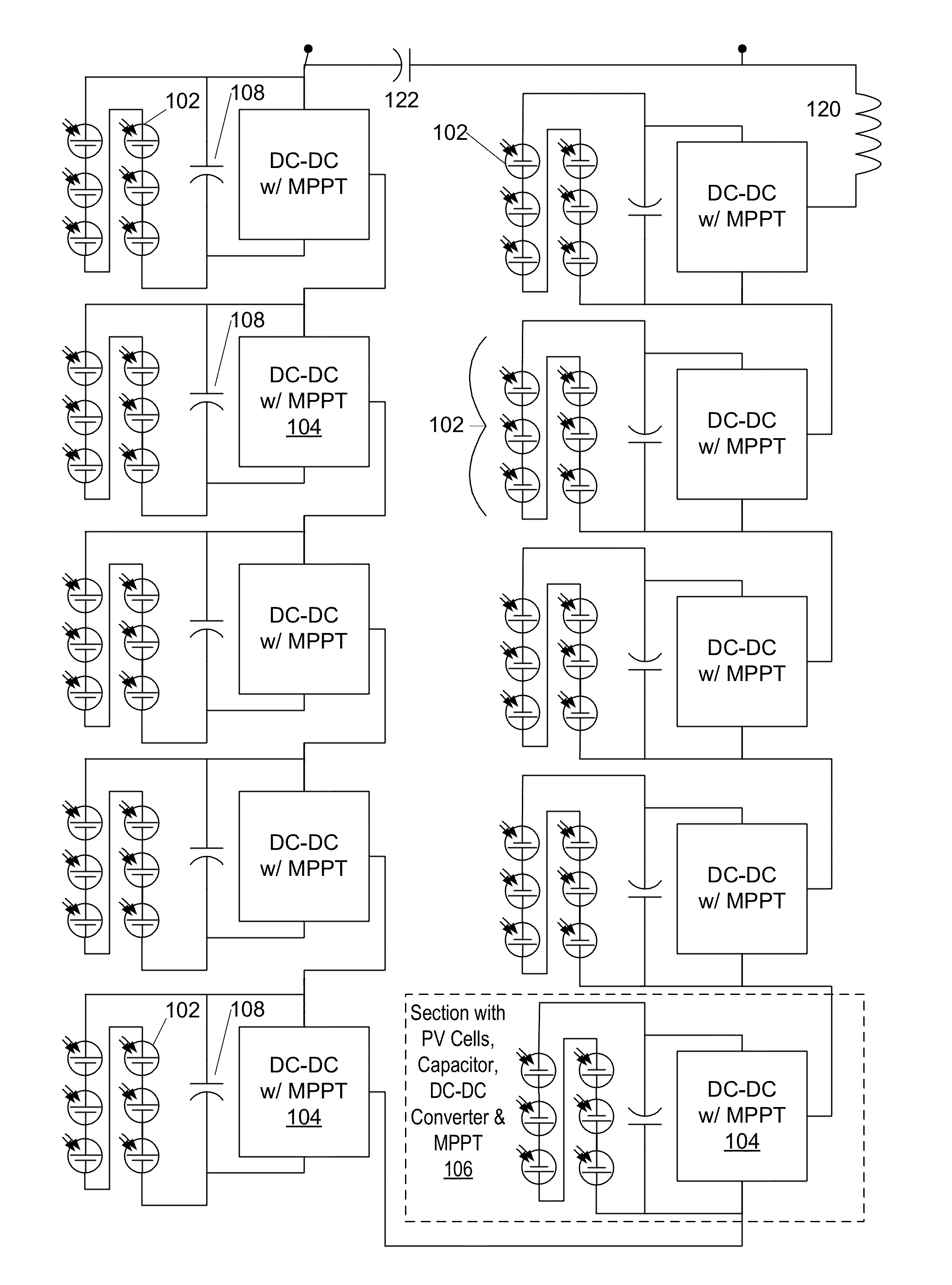
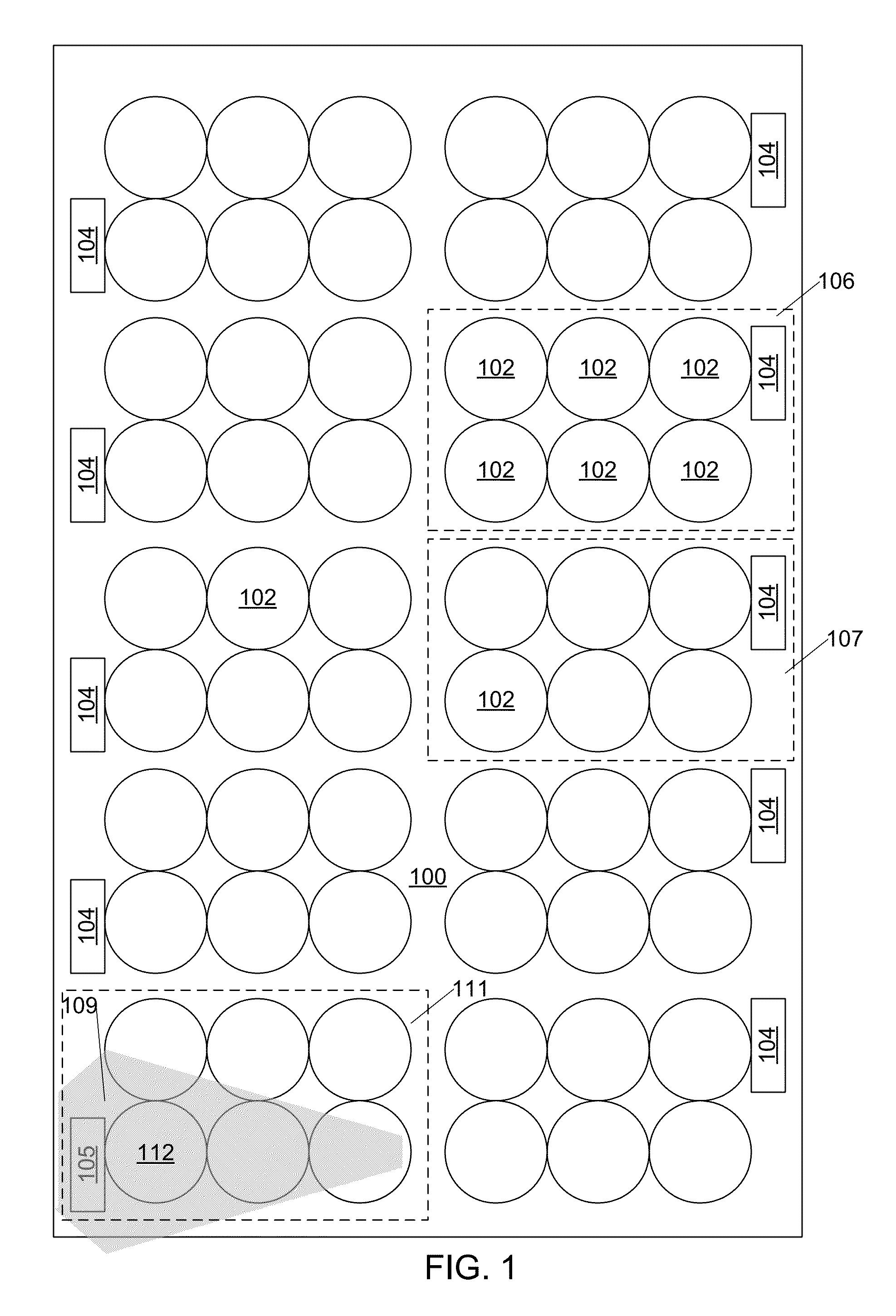
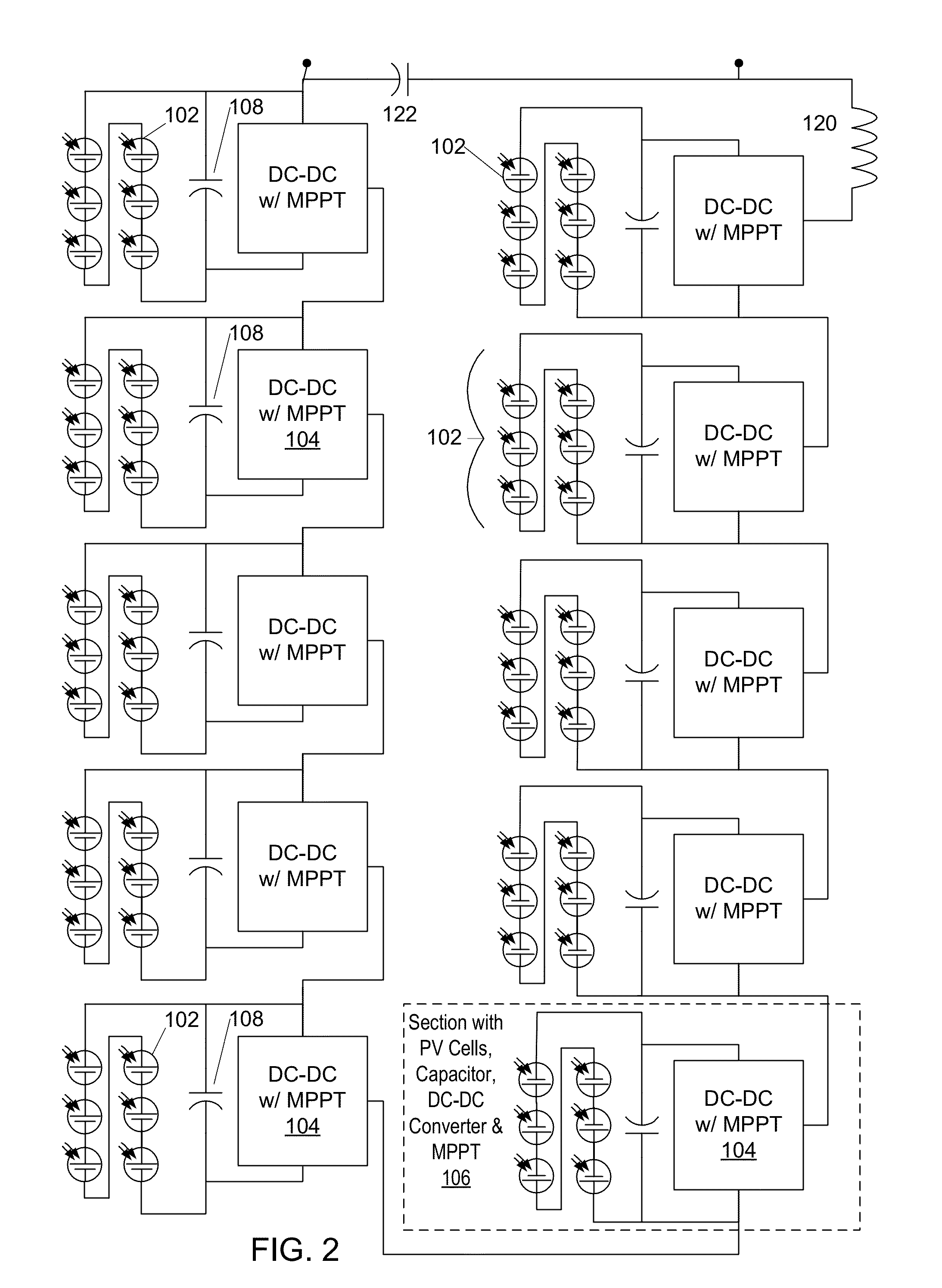
[0033]An integrated photovoltaic (PV) panel 100 is illustrated in FIG. 1. This panel has a quantity of PV cell units 102, such as may be manufactured from single-crystal silicon, although alternative embodiments may have PV cell units comprising other materials including II-VI, III-V, and materials such as copper indium gallium diselenide. In an embodiment, the PV cell units are fabricated as single cells, in an alternative embodiment each of the cell units are constructed of multiple PV cells in single-layer or multiple-layer form and may have integrated series and / or parallel interconnect internal to each cell unit. Each cell unit has at least one positive terminal and at least one negative terminal through which power generated from light incident on the cell unit can be extracted from the cell unit.

[0034]The cell units 102 are organized into several sections, such as section 106 and section 107, where each section has at least one cell unit 102, and typically has several cell un...


PUM


Abstract

An integrated photovoltaic panel has one or more integral DC-DC converter circuits. The DC-DC converter input port couples to a section of at least one photovoltaic (PV) device of the panel separate from PV devices feeding other converters. The converter has an MPPT controller for operating the converter to transfer maximum power from coupled photovoltaic devices to its output port. The PV panel has a transparent substrate to which PV devices are mounted. A laminating material seals PV devices and converters to the substrate. In embodiments, the panel has multiple converters connected with output ports in series. The integrated PV panel provides summed maximum powers of each section of PV devices. In some embodiments the DC-DC converters are complete with inductors, in other embodiments a common inductor is shared by multiple converters of the panel, in a particular embodiment the common inductor is parasitic inductance of the panel.

Description

RELATED APPLICATIONS[0001]This application claims benefit of priority to U.S. Provisional Patent Application Ser. No. 61 / 553,513, filed Oct. 31, 2011, which is incorporated herein by reference.[0002]Further discussion of panel-wide energy-storage inductors with incomplete, inductorless, buck-type DC-DC converters is available in U.S. Provisional Patent Application Ser. No. 61 / 375,012 filed Aug. 18, 2010, the contents of which are incorporated herein by reference.FIELD[0003]The present document relates to the field of photovoltaic panels with integral electronics.BACKGROUND[0004]Photovoltaic (PV) panels are often used to recharge batteries, or to provide power to the grid through grid-tie inverters. PV panels often, however, provide less output power than expected from known device efficiency and illumination.[0005]One reason that PV panels may deliver less than optimum power is that their best power output under typical conditions is often at a voltage that is not well matched to ba...

Claims


Application Information

Patent Timeline
Patent Type & Authority Applications(United States)
IPC IPC(8): H02J1/00H01L31/0224
CPCH01L31/0504H01L31/0201H02S40/32H02J3/385Y02E10/58H01L31/02021H02J2300/26H02J3/381Y02E10/56H02J3/46
Inventor JERGOVIC, ILIJAYAO, KAIWEISTRATAKOS, ANTHONY J.
Owner VOLTERRA SEMICONDUCTOR
Why Eureka
Try Eureka